
Thermal throttling of electronic devices

a technology of electronic devices and thermal throttling, applied in the direction of electric controllers, instruments, controllers with particular characteristics, etc., can solve the problems of affecting the operation efficiency of high-performance computing devices, generating significant amounts of heat during operation, and affecting the efficiency of heat dissipation measures,

Active Publication Date: 2019-04-30
INTEL CORP
View PDF12 Cites 16 Cited by
  • Summary
  • Abstract
  • Description
  • Claims
  • Application Information

AI Technical Summary

Benefits of technology

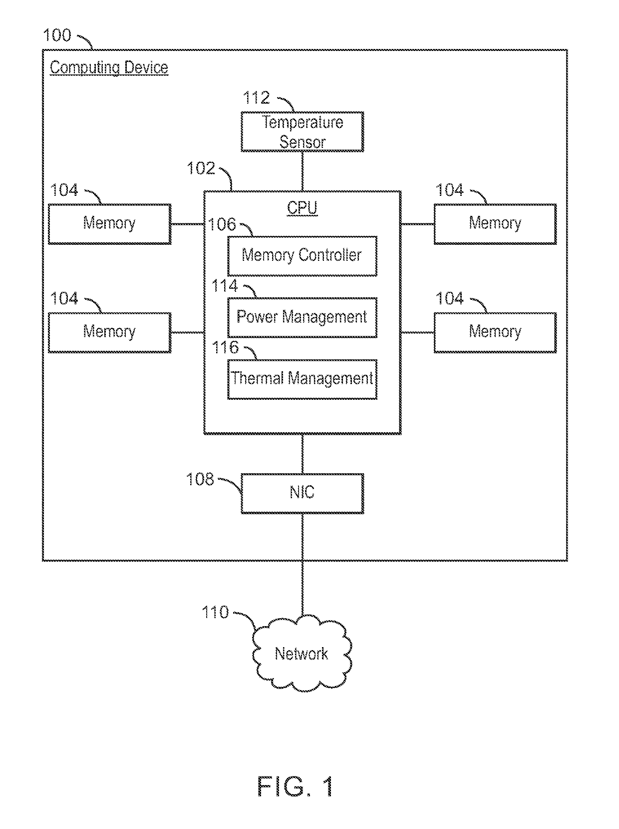
The present patent relates to techniques for protecting electronic devices from excessive heat and damage caused by excessive heat. More specifically, the patent describes a method for throttling the performance of a memory device in a computing system to maintain acceptable thermal characteristics. The technique involves detecting the temperature of the memory device and reducing its performance to prevent damage. The patent also describes a computing device that includes a CPU and a memory device, and a memory controller that can communicate with other devices through a network. The technical effects of the patent include reducing the risk of damage to electronic devices and maintaining optimal performance levels expected by users.

Problems solved by technology

High performance computing devices tend to generate significant amounts of heat during operation.
Excessive heat can damage some electronics or may result in error.
However, as computing devices become more compact, these heat dissipation measures tend to be less effective.

Method used


Image

  • Thermal throttling of electronic devices
  • Thermal throttling of electronic devices
  • Thermal throttling of electronic devices

Examples


example 1

[0059 is a computing device to perform thermal throttling. The computing device includes an electronic component; a temperature sensor thermally coupled to the electronic component; and a thermal management controller to receive a temperature measurement from the temperature sensor and generate a throttling factor for the electronic component. If the temperature measurement is greater than a specified threshold, the throttling factor is to reduce performance of the electronic component to be at least a performance guarantee for the electronic component.

example 2

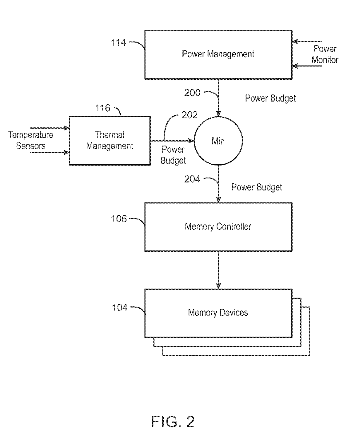
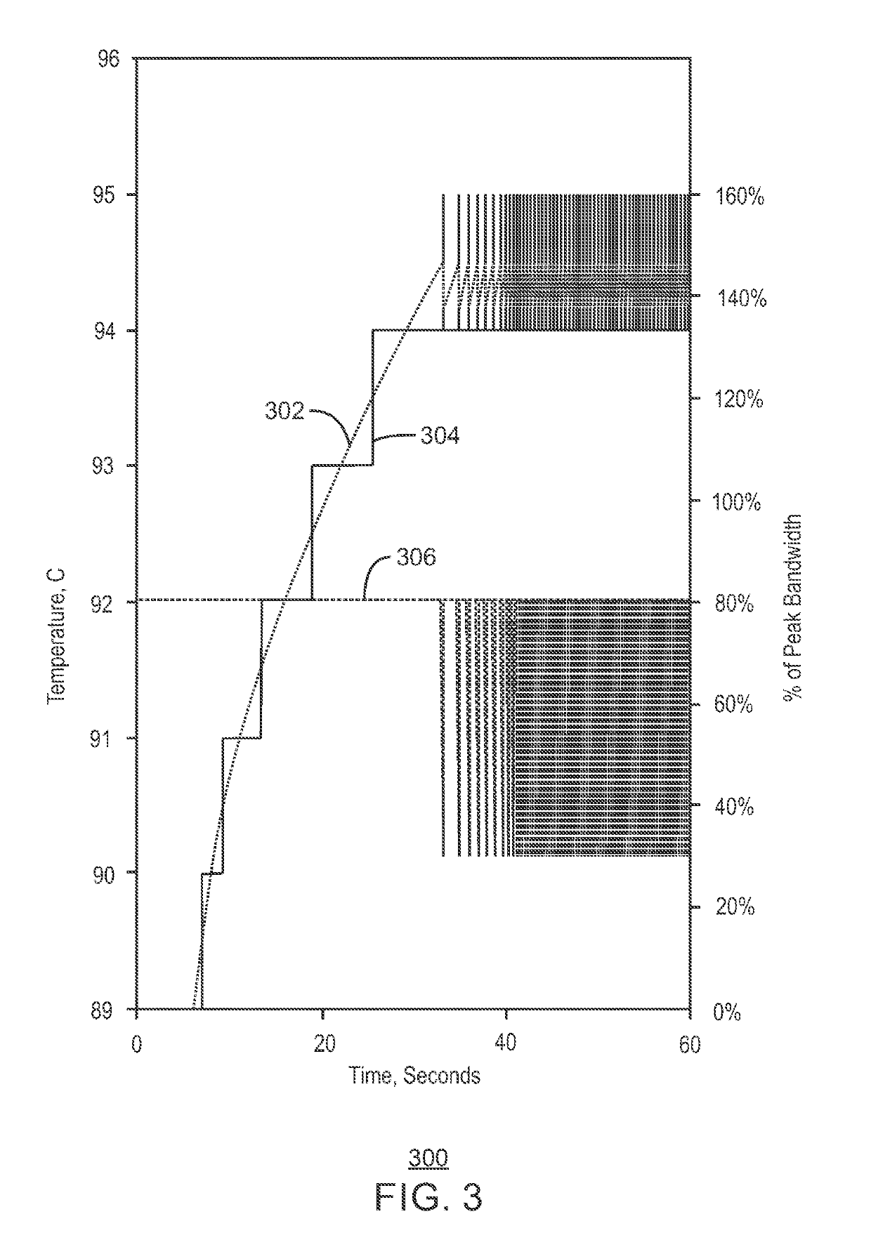
[0060 includes the computing device of example 1, including or excluding optional features. In this example, the thermal management controller is to compute the throttling factor using an algorithm with three temperature thresholds. Optionally, the three temperature thresholds comprise: a first temperature threshold that is a maximum junction temperature specified for the electronic component; a third temperature threshold that is the specified threshold, which corresponds with the performance guarantee; and a second temperature threshold between the first temperature threshold and the third temperature threshold. Optionally, a difference between the first temperature threshold and the second temperature threshold is equal to a measurement resolution of the temperature sensor. Optionally, a difference between the second temperature threshold and the third temperature threshold is equal to a measurement resolution of the temperature sensor. If the temperature measurement is greater t...

example 3

[0061 includes the computing device of any one of examples 1 to 2, including or excluding optional features. In this example, the throttling factor is a percentage of the maximum power which can be consumed on the electronic component.


PUM


Abstract

Disclosed herein is a computing device configured to implement thermal throttling of a component of the computing device. The computing device includes an electronic component and a temperature sensor thermally coupled to the electronic component. The computing device also includes a thermal management controller to receive a temperature measurement from the temperature sensor and generate a throttling factor for the electronic component. If the temperature measurement is greater than a specified threshold, the throttling factor is to reduce performance of the electronic component to be at least the performance guarantee for the electronic component.

Description

TECHNICAL FIELD[0001]The present disclosure relates to thermal protection for memory devices. More specifically, the present disclosure describes techniques for throttling the performance of a memory device based on detected junction temperature.BACKGROUND ART[0002]High performance computing devices tend to generate significant amounts of heat during operation. Excessive heat can damage some electronics or may result in error. Therefore, various techniques exist for dissipating the heat through the use of heat sinks, heat pipes, fans, and the like. However, as computing devices become more compact, these heat dissipation measures tend to be less effective. In some cases, processors such as central processing units (CPUs) are throttled to avoid excessive temperatures. In a typical throttling arrangement, the clock frequency of the CPU can be reduced to reduce the amount of generated heat.BRIEF DESCRIPTION OF THE DRAWINGS[0003]FIG. 1 is a block diagram of a computing device configured...

Claims


Application Information

Patent Timeline
Patent Type & Authority Patents(United States)
IPC IPC(8): G06F1/20G06F1/3234G06F1/324G06F1/3206G06F1/32G06F1/3225
CPCG06F1/206G06F1/324G06F1/3206G06F1/3225G06F1/3234G06F1/3275Y02D10/16G06F2212/1028Y02D10/126Y02D10/13Y02D10/14G06F1/20G06F11/3037G06F11/3058G06F11/3062G06F11/3457G11C7/04G11C2029/0409Y02D10/00G05B11/42
Inventor KAM, TIMOTHY Y.AHUJA, SANDEEPAGARWAL, RAJATSODANI, AVINASHSUH, JINHOCHINTHAMANI, MEENAKSHISUNDARAM
Owner INTEL CORP
Learn More