Device and method for estimating a flow of gas in an enclosure maintained at reduced pressure in relation to the gas

a technology of gas flow and enclosure, which is applied in the direction of permeability/surface area analysis, instruments, suspensions and porous materials, etc., can solve the problems of reliability of measurement, particularly long time lags, etc., and achieves the effect of reducing time, more sensitive, and more reliabl

Active Publication Date: 2019-05-07
COMMISSARIAT A LENERGIE ATOMIQUE ET AUX ENERGIES ALTERNATIVES
View PDF27 Cites 0 Cited by
  • Summary
  • Abstract
  • Description
  • Claims
  • Application Information

AI Technical Summary

Benefits of technology

[0028]One purpose of the present invention is to provide a method and a device allowing the change over time of one or several gas flow(s) in an enclosure, or volume, maintained in a low pressure regimen relative to the gas(es) measured, to be reliably simulated and with a shortened time. One purpose of the present invention is also to be able to perform an estimation of a permeation of a barrier layer by making this measurement more sensitive, more reliable and with a shortened time with respect to that necessary to devices and methods of prior art for measuring a permeation for estimating permeation properties of the barrier layer.
[0039]The method according to the invention enables the gas flow within the enclosure to be characterized without necessarily having to wait for the steady state regimen of this flow to deduce therefrom a value of the parameters A and B which enable this gas flow to be characterized. Moreover, the estimation reliability of this gas flow is improved because it is no longer possible to unintentionally truncate the permanent flow characteristic of the target gas being measured, that is the transfer rate, before the steady state regimen is reached. The estimation of the values of the parameters A and B is iteratively performed by approaching at best the estimation Jestim(t) of the measurement of the gas flow performed for Jmeasurement.
[0063]The values of the parameters A and B may be decreased or increased by a variable pitch the value of which depends on previous decreases or increases of the values of the parameters A and B. Thus, it is possible to shorten the time of implementation of the method to obtain estimations of the values of the parameters A and B.
[0078]Thus, this method enables the change over time of the background noise to be efficiently simulated before performing the permeation measurement of the barrier layer. Indeed, during the first implementation of the method for estimating the gas flow, this gas flow corresponds to a measurement of a background noise in the second chamber (corresponding to the gas flows from the walls of the second chamber, from the different degassings of the measuring device as well as from the degassing of the barrier layer). During the second implementation of the method for estimating the gas flow, the measured gas flow Jmeasurement thus corresponds to the sum of the flows from the background noise Jdegas_estim, that is the degassings occurring in the second chamber, and the flow from the gas permeation through the barrier layer Jperm_measurement. By subtracting the estimation of the gas flow Jdegas_estim(t) from the measured gas flow Jmeasurement during the estimation of the parameters A and B, the measurement sensitivity of the gas flow corresponding to the permeation through the barrier layer is thus dramatically improved.

Problems solved by technology

Thus, the barrier layers do not totally prevent the gases from passing therethrough and thus have a non-zero permeation relative to gases.
First, as regards the sensitivity of the measurement performed, the detection of the flow of the target gas 18 developing through the barrier layer 10 by the measuring device 16 is only possible if the signal to background noise ratio is in accordance with the detection capabilities of the measuring device 16, that is if the value of the measured signal corresponding to the gas flow 18 through the layer 10 is high enough to be distinct from the background noise present in the second chamber 14. This background noise comes from several factors:the minimum electronic noise, or sensitivity of the measuring device 16, such as the minimum ionization current detectable by a mass spectrometer for the isotope of the target gas considered;the presence of residual target gas in the second chamber 14 coming in particular from the degassing from the walls of the second chamber 14 and from the layer 10 the permeation of which is attempted to be measured (and also the filament of the mass spectrometer in the case of a measurement by such an apparatus.
Indeed, materials having high barrier properties can include transient state regimens (and thus “Time lags”) which are particularly lengthy, that can range up to several months.
Finally, a third factor complexifying the implementation of such a measurement is the reliability of the measurement performed.
These drawbacks are also found when a measurement of a gas flow is desired to be performed in an enclosure maintained in a low pressure regimen relative to the gas(es) to be measured, regardless of whether this flow corresponds to a rise in pressure of the target gas in the enclosure or to a decrease in the residual pressure of the gas within the enclosure (corresponding for example to a degassing in the enclosure, that is to the background noise).

Method used


Image

  • Device and method for estimating a flow of gas in an enclosure maintained at reduced pressure in relation to the gas
  • Device and method for estimating a flow of gas in an enclosure maintained at reduced pressure in relation to the gas
  • Device and method for estimating a flow of gas in an enclosure maintained at reduced pressure in relation to the gas

Examples


Embodiment Construction

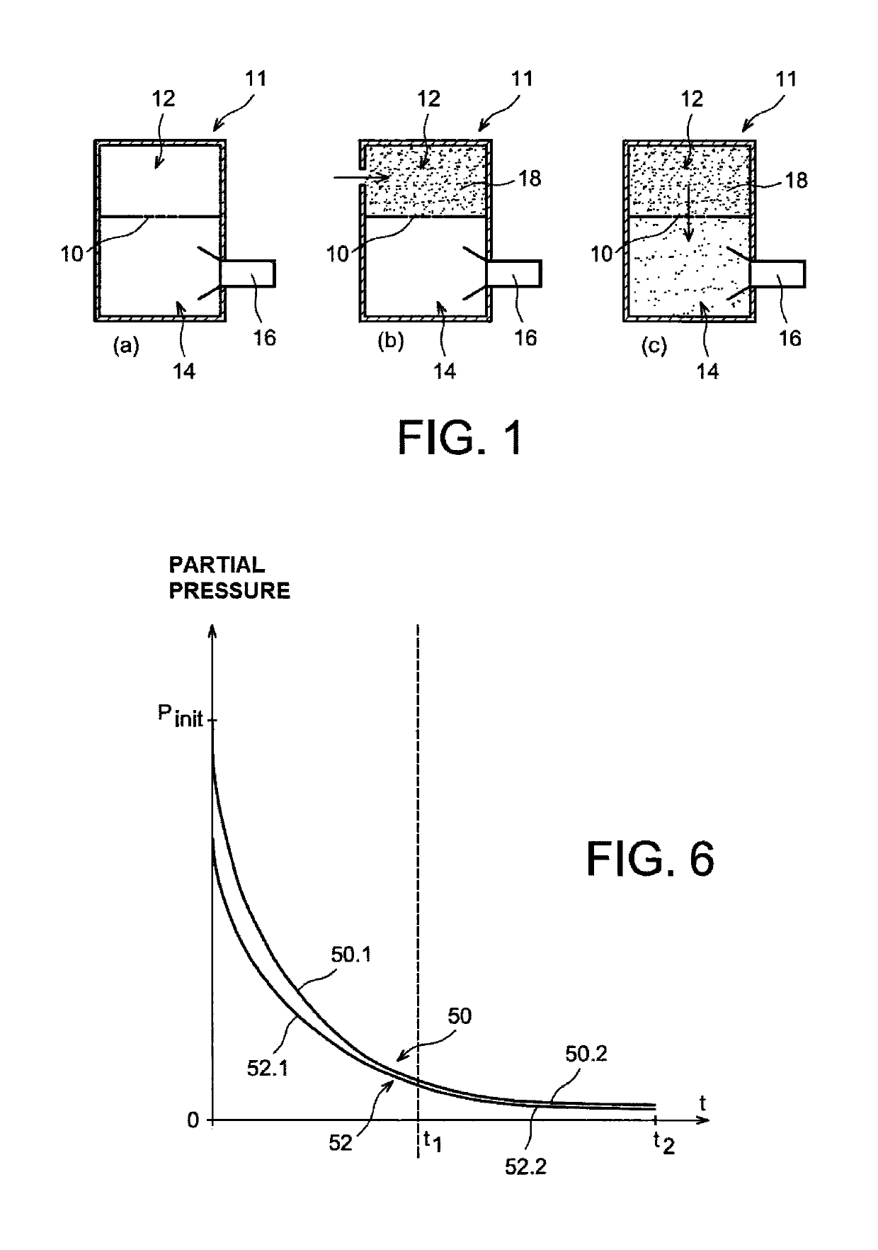
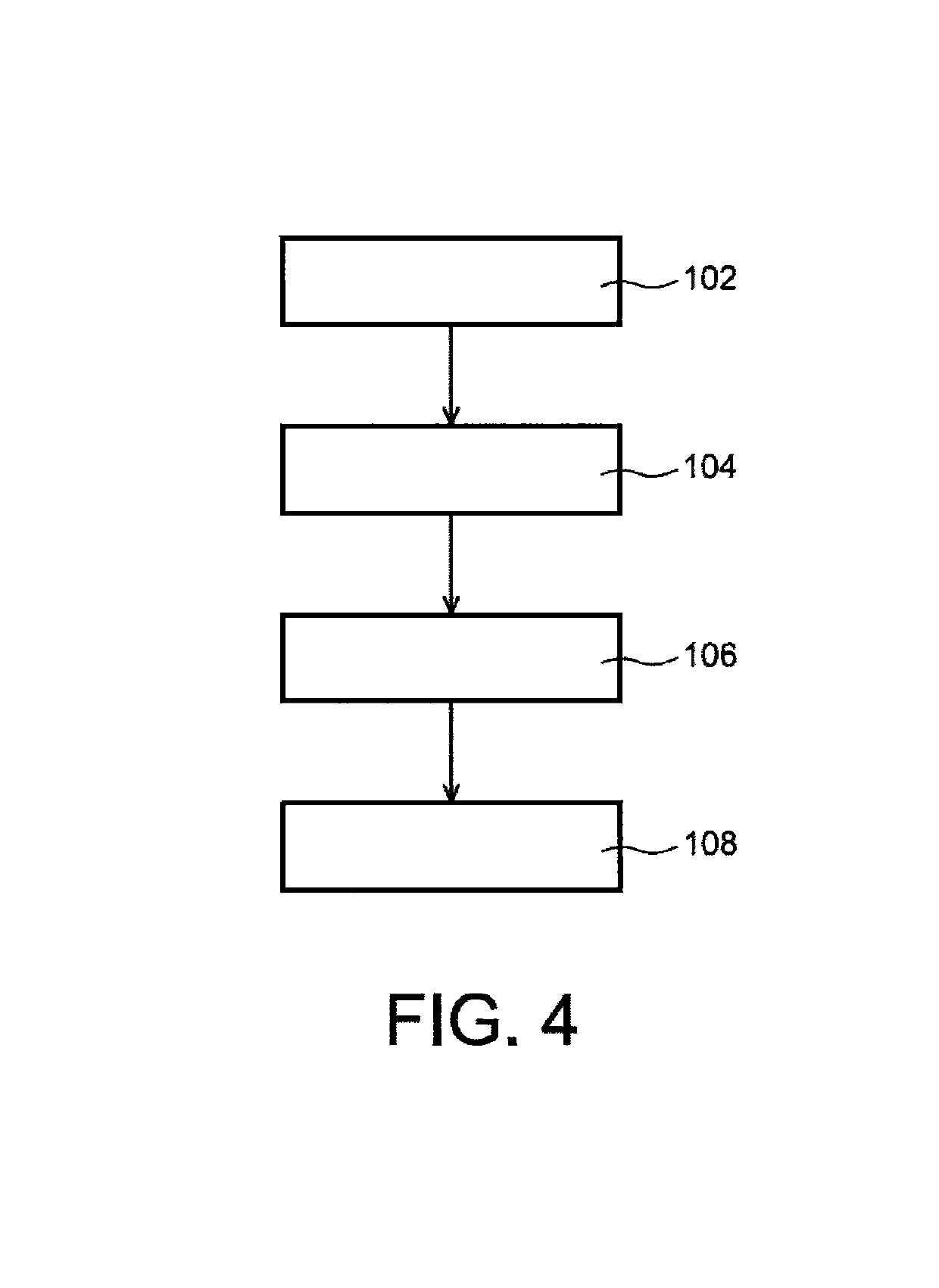
[0097]The implementation of a method for estimating the permeation of a barrier layer 10, or barrier film, having in particular barrier properties relative to one or more gases is described according to a particular embodiment. The gas(es) considered here is (are) for example water vapor, dioxygen, one of the water or oxygen isotopes, helium, hydrogen or a mixture of at least two of these gases. This method is implemented using in particular a permeameter 11 as previously described in connection with FIG. 1. The different steps of this method are shown in FIG. 4 as a diagram.

[0098]A first step of this method is to calculate an estimation of the change over time of the background noise in the detection enclosure of the permeameter 11, that is in the second chamber 14 of the permeameter 11 (step 102). This estimation of the background noise is to estimate the change over time of the gas flow in the enclosure formed by the second chamber 14 and which corresponds to a pressure decrease ...


PUM

PropertyMeasurementUnit
pressureaaaaaaaaaa
permeationaaaaaaaaaa
pressureaaaaaaaaaa

Abstract

Method for estimating a gas flow in an enclosure maintained in a low pressure regimen relative to the gas, including:measuring, as a function of time, a gas flow Jmeasurement in the enclosure, andestimating values of the parameters A and B iteratively implemented by decreasing an estimation error based on a difference between Jestim(t) and Jmeasurement,and wherein, when Jmeasurement corresponds to a pressure rise of the gas in the enclosure, Jestim(t) is calculated according to the equation:Jestim⁡(t)=2⁢A⁢∑n=1n⁢⁢ma⁢⁢x⁢(Bπ⁡(t-OffX))12⁢exp⁡(-2⁢(n+1)24⁢B⁡(t-OffX))+OffYand when Jmeasurement corresponds to a pressure decrease of the gas in the enclosure, Jestim(t) is calculated according to the equation:Jestm⁡(t)=Pinit-2⁢A⁢∑n=1n⁢⁢ma⁢⁢x⁢(Bπ⁡(t-OffX))12⁢exp⁡(-(2⁢n+1)24⁢B⁡(t-OffX))+OffYFIG. 1.

Description

TECHNICAL FIELD[0001]The invention relates to a device and a method for estimating at least one gas flow in an enclosure maintained in a low pressure regimen relative to the gas(es). The invention is applicable in particular for estimating the permeation, that is gas barrier properties, of a barrier layer, or barrier film.STATE OF PRIOR ART[0002]Some devices, such as electronic components and photovoltaic panels comprising organic materials, are particularly sensitive to oxidation induced by water and dioxygen. In order to be able to increase the lifetime of these devices, it is required to protect them at the most by using barrier films, or barrier layers, having strong water vapor and dioxygen barrier properties, for example between about 10−3 g·m−2·day−1 and 10−6 g·m−2·day−1 for Water Vapor Transmission Rate (WVTR) and in the order of 10−3 cm3·m−2·days−1 for Oxygen Transmission Rate (OTR). Such barrier films are for example “Ultra Barrier Solar Film” marketed by 3M™ Company, or X...

Claims


Application Information

Patent Timeline
Patent Type & Authority Patents(United States)
IPC IPC(8): G01F1/50G01N15/08
CPCG01N15/0826G01F1/50
Inventor LEROY, ARNAUDCROS, STEPHANE
Owner COMMISSARIAT A LENERGIE ATOMIQUE ET AUX ENERGIES ALTERNATIVES
Why Eureka
Try Eureka