
Method of manufacturing cigs-based solar cell and cigs-based solar cell

a solar cell and cigs technology, applied in the field of manufacturing a cigs-based solar cell, can solve the problems of reducing the increasing the importance of the development of next-generation clean energy sources, and rapidly increasing the cost of silicon, so as to reduce the amount of ga2o3 formed and maintain the effect of photoelectric conversion efficiency of the solar cell

Active Publication Date: 2019-05-07
KOREA INST OF ENERGY RES
View PDF9 Cites 0 Cited by
  • Summary
  • Abstract
  • Description
  • Claims
  • Application Information

AI Technical Summary

Benefits of technology

[0008]Accordingly, the present invention has been made keeping in mind the above problems occurring in the related art, and an object of the present invention is to provide a CIGS-based solar cell, which prevents a reduction in efficiency caused by the formation of Ga2O3 even though the CIGS-based solar cell includes a transparent rear electrode including a TCO material, and a method of manufacturing the same.
[0010]In the method of manufacturing the CIGS-based solar cell according to the present invention, the metal rear electrode patterns provided with the light-transmissive portion are formed on the surface of the rear electrode layer including the TCO material, thus reducing the amount of Ga2O3 formed between the rear electrode layer and the light absorption layer. Even though Ga2O3 is formed, since current flows through the rear electrode patterns, the interfacial resistance between the rear electrode layer and the light absorption layer is prevented from being increased. Thus, even though the rear electrode including the TCO material is used, the photoelectric conversion efficiency of the solar cell is maintained.
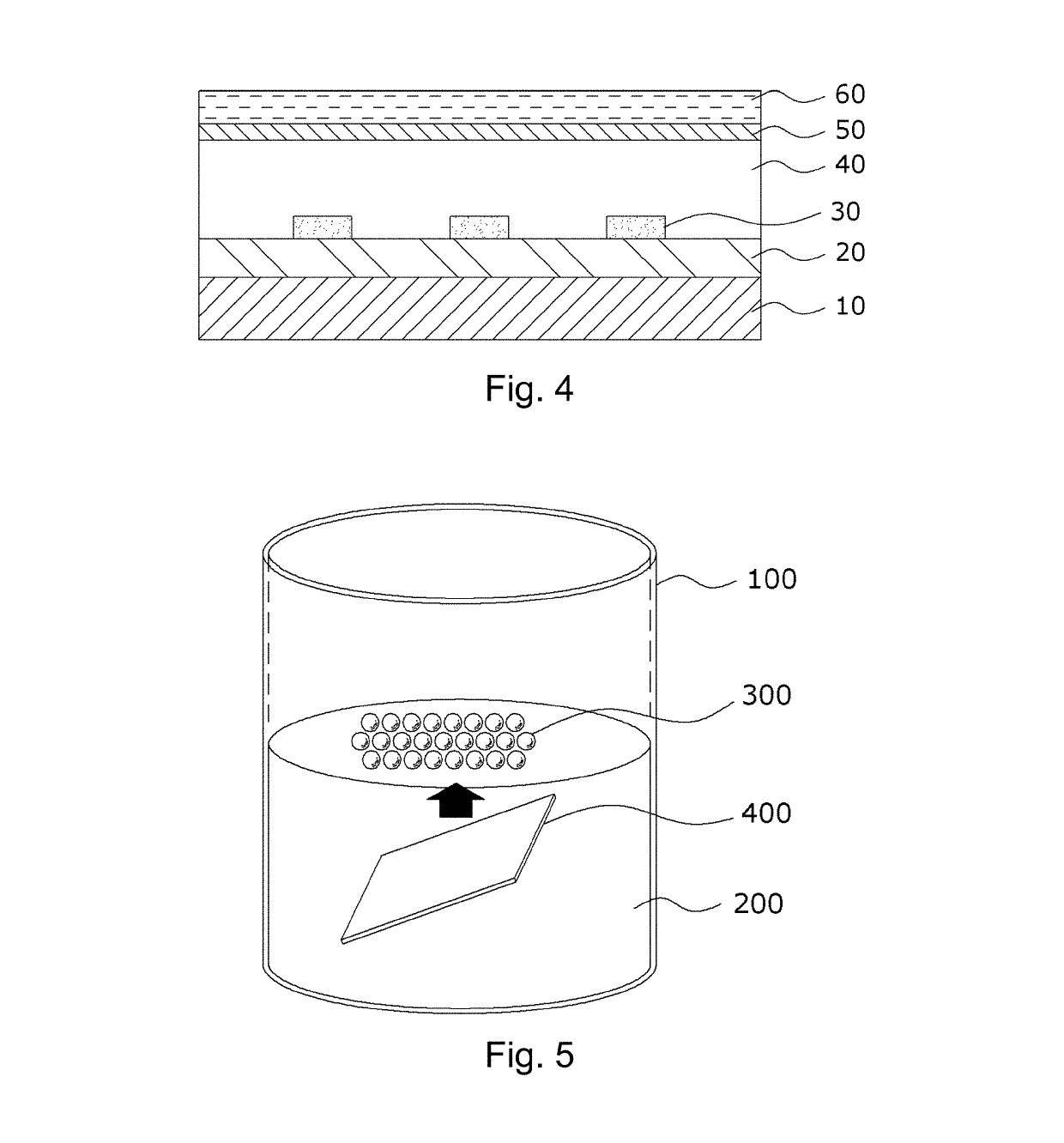
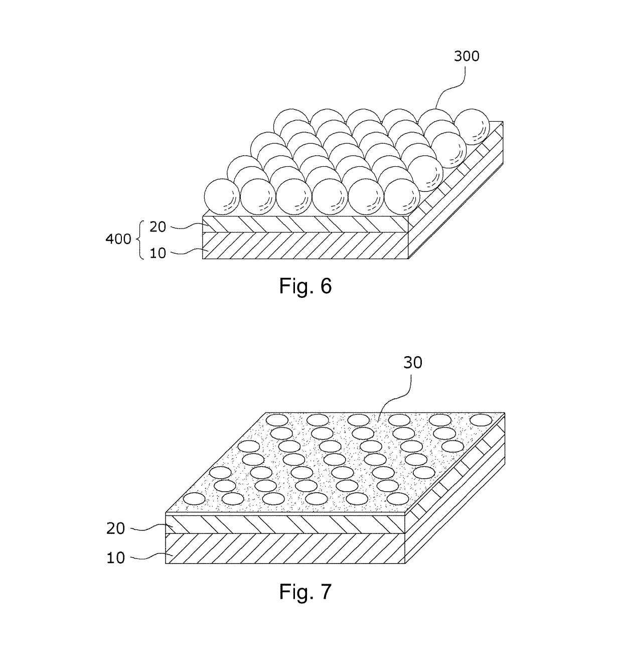
[0013]In the case where the rear electrode patterns are formed using the above-described method, when the spherical particles are selected, the particle size may be controlled so as to control the size of the rear electrode patterns. Specifically, the width of the pattern and the size of the light-transmissive portion, which is the interval between the patterns, are increased as the size of the selected spherical particle is increased. Conversely, the width of the pattern and the size of the light-transmissive portion are reduced as the size of the spherical particle is reduced.
[0014]Alternatively, after the attaching the spherical particles, the size of the spherical particle may be controlled to thus control the size of the rear electrode pattern. When the surface of the spherical particle is etched after the attaching the spherical particles to reduce the volume of the spherical particle, the width of the pattern is increased but the size of the light-transmissive portion, which is the interval between the patterns, is reduced. In addition, when the spherical particles are stuck together after the attaching the spherical particles, the width of the pattern is reduced but the area occupied by the light-transmissive portions per unit area of the rear electrode layer is increased.
[0015]When the spherical particles include a polystyrene material, the spherical particles may be attached and then immersed in an organic solvent such as acetone to be stuck together and highly densified, and thus the area occupied by the spherical particles per unit area of the rear electrode layer may be increased.
[0020]According to the present invention having the above-described constitution, the metal rear electrode patterns provided with the light-transmissive portion are formed on the surface of the rear electrode layer including the TCO material, thus reducing the amount of Ga2O3 formed between the rear electrode layer and the light absorption layer. Even though Ga2O3 is formed, since current flows through the rear electrode patterns, the interfacial resistance between the rear electrode layer and the light absorption layer is prevented from being increased. Thus, even though the rear electrode including the TCO material is used, the photoelectric conversion efficiency of the solar cell is maintained.

Problems solved by technology

Recently, the importance of the development of next-generation clean energy sources has increased due to serious environmental pollution and the depletion of fossil fuels.
However, there is growing interest in a thin-film solar cell due to the currently rapidly increasing cost of silicon, attributable to the short supply thereof.
However, a TCO material, which is most frequently used as a transparent electrode in recent years, has a drawback in that, since the TCO material is reacted with Ga contained in CIGS to form Ga2O3, the specific resistance of a CIGS-based solar cell including a transparent rear electrode is increased, thus greatly reducing the efficiency of the solar cell.
Furthermore, when a CIGS layer is formed in order to prevent the formation of Ga2O3, which is considered to be a problem, a process for forming the CIGS layer is limitative, thus reducing the efficiency of the solar cell.

Method used


Image

  • Method of manufacturing cigs-based solar cell and cigs-based solar cell
  • Method of manufacturing cigs-based solar cell and cigs-based solar cell
  • Method of manufacturing cigs-based solar cell and cigs-based solar cell

Examples


Embodiment Construction

[0029]A detailed description will be given of embodiments of the present invention, with reference to the appended drawings.

[0030]The structure and the manufacture of a double-sided transmission CIGS solar cell of the present invention will be described using the embodiments below.

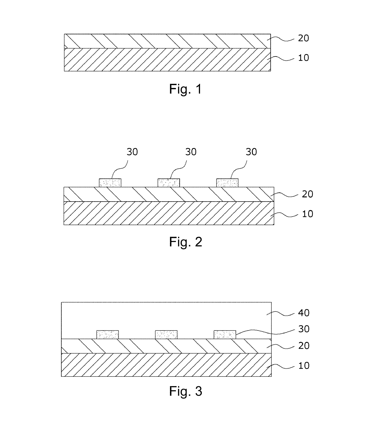
[0031]FIGS. 1 to 4 are views showing a process for manufacturing the double-sided transmission CIGS solar cell according to the embodiment of the present invention.

[0032]In the present embodiment, first, a rear electrode layer 20 including a TCO material is formed on the surface of a transparent substrate 10.

[0033]Representative examples of the transparent substrate 10 may include a glass substrate including a soda lime glass material but are not limited thereto, and various transparent materials may be applied to the substrate.

[0034]The rear electrode layer 20 includes a transparent TCO (transparent conducting oxide) material so that light is transmitted through a lower part thereof, unlike the related ar...


PUM


Abstract

A method of manufacturing a CIGS-based solar cell including a transparent rear electrode, the method comprising forming a rear electrode layer including a transparent oxide material; forming rear electrode patterns including a metal material on the rear electrode layer; forming a CIGS-based light absorption layer on the rear electrode layer on which the rear electrode patterns are formed; forming a buffer layer on the light absorption layer; and forming a front electrode including a transparent material on the buffer layer, wherein the rear electrode patterns are provided with a transmissive portion, through which light is transmitted, formed between patterns of the metal material.

Description

CROSS-REFERENCE TO RELATED APPLICATION[0001]This application claims the priority benefit of Korean Patent Application No. 10-2016-0153512, filed on Nov. 17, 2016 in the Korean Intellectual Property Office, the disclosure of which is incorporated herein by reference.BACKGROUND OF THE INVENTION1. Field of the Invention[0002]The present invention relates to a method of manufacturing a CGIS-based solar cell and a CIGS-based solar cell, and more particularly to a CIGS-based solar cell which uses light incident on a lower part thereof, thereby being applicable to a double-sided solar module or a tandem solar module, and a method of manufacturing the same.2. Description of the Related Art[0003]Recently, the importance of the development of next-generation clean energy sources has increased due to serious environmental pollution and the depletion of fossil fuels. A solar cell is a device that directly converts solar energy into electric energy. The solar cell incurs insignificant pollution,...

Claims


Application Information

Patent Timeline
Patent Type & Authority Patents(United States)
IPC IPC(8): H01L31/0224H01L31/054H01L31/0392H01L31/18H01L31/032H01L31/0687
CPCH01L31/022441H01L31/022466H01L31/022475H01L31/022483H01L31/0322H01L31/0543H01L31/0547H01L31/0687H01L31/1884H01L31/03923Y02P70/521Y02E10/544Y02E10/52Y02E10/541Y02P70/50H01L31/02366H01L31/042H01L31/0749H01L31/18Y02E10/50
Inventor KIM, KIHWANYUN, JAE-HOGWAK, JIHYEAHN, SEUNG-KYUCHO, JUN-SIKPARK, JOO-HYUNGEO, YOUNG-JOOYOO, JIN-SUAHN, SE-JINCHO, ARA
Owner KOREA INST OF ENERGY RES
Learn More