COA array substrate and liquid crystal display panel

a liquid crystal display panel and array substrate technology, applied in non-linear optics, instruments, optics, etc., can solve the problems of affecting display effects, increasing process difficulty, and reducing product yield

Active Publication Date: 2019-05-14
WUHAN CHINA STAR OPTOELECTRONICS TECH CO LTD
View PDF12 Cites 0 Cited by
  • Summary
  • Abstract
  • Description
  • Claims
  • Application Information

AI Technical Summary

Benefits of technology

[0006]In view of such deficiencies in the prior art, this disclosure provides a COA array substrate, can effectively reduce the gas remaining in the color filter layer to penetrate into the liquid crystal layer to form bubble defects. To achieve the above goal, this disclosure uses the following technical solution:
[0017]Compared to the prior art, the COA array substrate provided by embodiment of this disclosure includes vent holes disposed through the portion of the color filter layer covering the non-display region correspondingly, first, during the process of preparing the color filter layer, the gas inside the color filter layer can be smoothly discharged through these vent holes, the amount of residual gas inside the color filter layer can be reduced; secondly after a liquid crystal display panel is formed into a complete package, if the liquid crystal display panel at a high temperature impact, high-voltage shock or external shock results in the case with a minute fluid passage between the liquid crystal layer and the color filter layer, at this time due to the presence of the vent holes with a relatively large pore size (with respect to the aforementioned minute fluid passage), the gas phase equilibrium is transferred from the interface of the liquid crystal layer to the vent holes, the small molecular gas released from interior of the color filter layer is difficult to penetrate into the liquid crystal layer, so that the formation of bubble defects can be avoided.

Problems solved by technology

In COA technology, forming the color filter layer directly on the array substrate increases the difficulty of the process, especially the problem that the residual gas in the color filter layer penetrates into the liquid crystal layer to form bubbles.
. . ) into the liquid crystal layer in the local formation of bubbles, this will affect the display effects and reduce product yield.
Therefore, for the COA technology, how to avoid the gas in the color filter layer to penetrate into the liquid crystal layer to form bubbles is a serious problem to be solved in the industry.

Method used


Image

  • COA array substrate and liquid crystal display panel
  • COA array substrate and liquid crystal display panel

Examples


Embodiment Construction

[0023]In order to make the objectives, technical solutions and advantages become more apparent, more detailed description of the present disclosure is made below with reference to the drawings and embodiments. It is to be understood that the specific embodiments explained herein are intended for the purpose of description only and shall not be used to limit the present disclosure.

[0024]Here, it should be noted that, in order to avoid unnecessary detail obscure this disclosure, the drawings only show a structure and / or processing steps closely related to the solutions according to this disclosure, and omit other details little relevant to this disclosure.

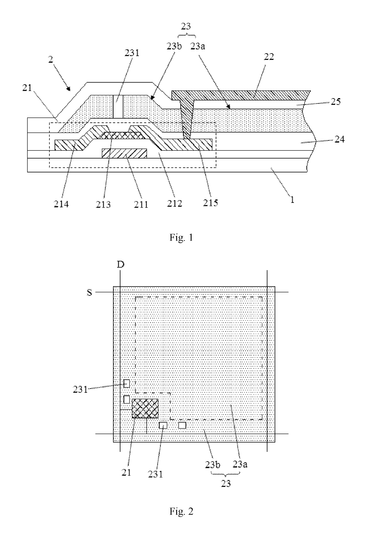
[0025]First, this embodiment provides a COA array substrate, see FIG. 1 and FIG. 2, the COA array substrate includes a base substrate 1, and an array of pixel structures 2 disposed on the base substrate 1 (the drawings only shows one of the pixel structures exemplarily).

[0026]The pixel structure 2 includes a scan line S, a data line ...


PUM

PropertyMeasurementUnit
diameteraaaaaaaaaa
lengthaaaaaaaaaa
thicknessaaaaaaaaaa

Abstract

This disclosure discloses a COA array substrate, including a base substrate, and an array of pixel structures disposed on the base substrate, wherein the pixel structure is provided with a color filter layer, the color filter layer includes a first portion and a second portion, the first portion of the color filter layer covers a display region of the pixel structure correspondingly, the second portion of the color filter layer covers a non-display region of the pixel structure correspondingly; in the second portion of the color filter layer is provided with vent holes. This disclosure also discloses a liquid crystal display panel, including an array substrate and a cell aligning substrate disposed oppositely, the liquid crystal molecules are disposed between the array substrate and the cell aligning substrate, wherein the array substrate described above uses the COA array substrate.

Description

TECHNICAL FIELD[0001]This disclosure relates to the field of display technology, in particular to a COA array substrate and a liquid crystal display panel containing a COA array substrate.DESCRIPTION OF RELATED ART[0002]Since the liquid crystal display device (LCD) has many advantages such as thin fuselage, low power, no radiation, it has been widely used, e.g. LCD TV, mobile phone, personal digital assistant (PDA), digital camera, computer screen or laptop screens.[0003]A LCD device typically includes a case, a liquid crystal display panel and a backlight module provided in the case. Wherein the structure of the liquid crystal display panel is mainly composed of a thin film transistor array (TFT Array) substrate, a color filter (CF) substrate, and a liquid crystal layer disposed between the two substrates, the operation principle is that application of driving voltage to the two glass substrates is carried out to control the rotation of the liquid crystal molecules of the liquid cr...

Claims


Application Information

Patent Timeline
Patent Type & Authority Patents(United States)
IPC IPC(8): G02F1/1333G02F1/1335G02F1/1368G02F1/1362
CPCG02F1/133345G02F1/1368G02F1/136227G02F1/133514G02F2201/503G02F2001/136222G02F1/136222
Inventor SUN, TAO
Owner WUHAN CHINA STAR OPTOELECTRONICS TECH CO LTD
Why Eureka
Try Eureka