
Trimming method, trimming circuity, and trimming system for integrated circuit with memory usage reduction

a technology of integrated circuits and trimming circuits, applied in the direction of thermoelectric devices, semiconductor/solid-state device testing/measurement, instruments, etc., can solve the problems of fluctuation of ics characteristics and the need for additional fuse usage in the conventional trimming process

Active Publication Date: 2019-05-21
NOVATEK MICROELECTRONICS CORP
View PDF12 Cites 2 Cited by
  • Summary
  • Abstract
  • Description
  • Claims
  • Application Information

AI Technical Summary

Benefits of technology

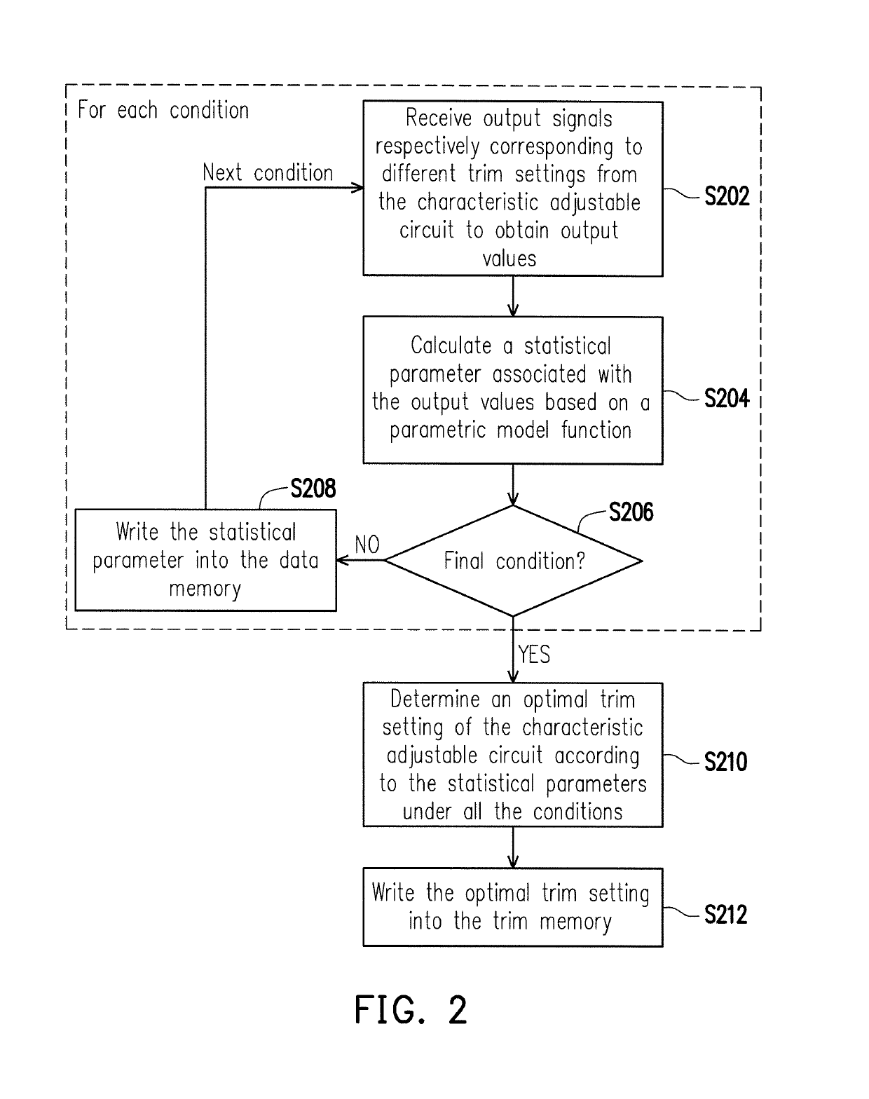
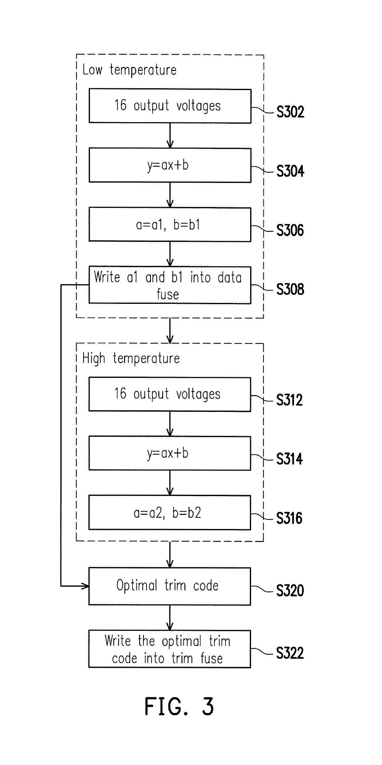
The present invention relates to a trimming method and system for an IC with memory usage reduction. The system includes a characteristic adjustable circuit, a tester, and a trimming circuitry. The trimming circuitry is coupled to the characteristic adjustable circuit and the tester and includes a characteristic outputting circuit, a data memory, and a trim memory. The method includes the steps of: under each condition, outputting signals respectively corresponding to different trim settings to obtain output values of the condition, calculating a statistical parameter of the condition based on a parametric model function, writing the statistical parameter of at least one of the conditions into the data memory, determining an optimal trim setting of the characteristic adjustable circuit based on the statistical parameters under all the conditions and writing the optimal trim setting into the trim memory. The technical effects of this invention include reducing memory usage and improving trimming efficiency.

Problems solved by technology

However, the characteristics of ICs may fluctuate due to external factors such as temperature and manufacture variations.
Nonetheless, the conventional trimming process would require additional fuse usage.

Method used


Image

  • Trimming method, trimming circuity, and trimming system for integrated circuit with memory usage reduction
  • Trimming method, trimming circuity, and trimming system for integrated circuit with memory usage reduction
  • Trimming method, trimming circuity, and trimming system for integrated circuit with memory usage reduction

Examples


Embodiment Construction

[0016]Some embodiments of the disclosure will now be described more fully hereinafter with reference to the accompanying drawings, in which some, but not all embodiments of the application are shown. Indeed, various embodiments of the disclosure may be embodied in many different forms and should not be construed as limited to the embodiments set forth herein; rather, these embodiments are provided so that this disclosure will satisfy applicable legal requirements. Like reference numerals refer to like elements throughout.

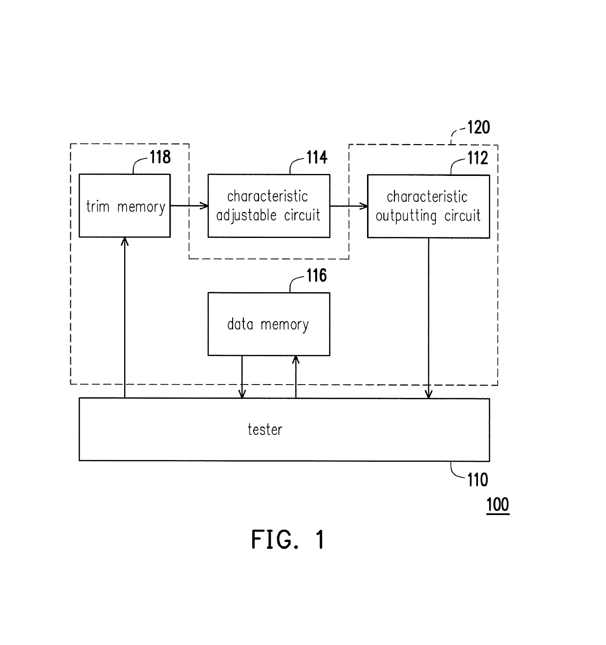
[0017]FIG. 1 illustrates a schematic diagram of a proposed trimming system in accordance with one of the exemplary embodiments of the disclosure. All components of the system and their configurations are first introduced in FIG. 1. The functionalities of the components are disclosed in more detail in conjunction with FIG. 2.

[0018]Referring to FIG. 1, an exemplary trimming system 100 would include, but not limited to, a tester 110, a characteristic adjustable circuit...


PUM


Abstract

The disclosure provides a trimming method, a trimming circuitry, and a trimming system for an IC with memory usage reduction. The method is applicable to a system including a tester, a characteristic adjustable circuit, and a trimming circuitry having a characteristic outputting circuit, a data memory, and a trim memory. The method includes the following steps. Under each condition, output signals respectively corresponding to trim settings are received from the characteristic adjustable circuit by the characteristic outputting circuit to obtain output values of the condition, a statistical parameter associated with the output values of the condition is calculated by the tester. The statistical parameter of at least one of the conditions is written into the data memory by the tester. An optimal trim setting of the characteristic adjustable circuit is determined according to the statistical parameters under all the conditions and written into the trim memory by the tester.

Description

TECHNICAL FIELD[0001]The disclosure relates to a trimming technique for an integrated circuit (IC) with memory usage reduction.BACKGROUND[0002]Numerous types of electronic devices and components are implemented by one or more ICs, and thus it is a necessity for ICs to possess physical and electrical characteristics with a high degree of precision. However, the characteristics of ICs may fluctuate due to external factors such as temperature and manufacture variations. To compensate for such variabilities, trimming techniques have been introduced where the characteristics of ICs are altered in order to deliver the perfonnance as promised in the IC specifications.[0003]A common trimming approach is to measure and record particular characteristics of each IC under different operating conditions, to thereby determine an optimal trim setting, and to burn the optimal setting into a fuse so that the characteristics of each IC could be optimally maintained irrespective of different operating...

Claims


Application Information

Patent Timeline
IPC IPC(8): G06F3/06G11C5/00H03L7/00G11C16/06H01L35/00H01L23/58H01L21/66G11C17/16G11C16/08G06F12/00H01L23/525G01P21/00
CPCH01L23/58H01L22/22H01L23/5256G11C17/165G11C17/16G01R31/30G01R31/28
Inventor SHIEH, TZONG-HONGEFANG, PO-HSIANG
Owner NOVATEK MICROELECTRONICS CORP
Learn More