Check patentability & draft patents in minutes with Patsnap Eureka AI!

Suspension of a tubular element in an aircraft compartment

a tubular element and aircraft compartment technology, applied in the direction of power plant cooling arrangments, target-seeking control, power installations, etc., can solve the problems of significant differences in relative positions, complex and expensive manufacturing parts with sufficient precision to align all the elements, and the position in which they are bolted

Active Publication Date: 2019-05-28
SAFRAN POWER UNITS
View PDF12 Cites 0 Cited by
  • Summary
  • Abstract
  • Description
  • Claims
  • Application Information

AI Technical Summary

Benefits of technology

The system effectively corrects misalignments, reduces assembly weight, and maintains proper ventilation and cooling while minimizing stress on structural components, ensuring efficient operation and longevity of the APU module.

Problems solved by technology

In this configuration, with the partition at the front of the tail cone setting a reference, the manufacturing tolerances of the various elements may result in significant differences in relative position between the nozzle of the APU and the mouth of the exhaust and / or between the rear end of the pipe and the opening in the tail cone into which it has to lead.
However, they may also be due to the structure of the tail cone, slight warping of which, for example, may significantly displace the position of the opening when the APU is correctly aligned relative the axis of the fuselage.
Manufacturing parts with sufficient precision to align all the elements proves to be complex and expensive.
An existing solution which involves fastening the upstream part of the pipe in the tail cone by means of plates having slots made therein that allow the position in which they are bolted to the structure to be adjusted proves unsatisfactory.
First, it does not always allow the mouth of the pipe to be aligned with the outlet of the nozzle without the other end of the pipe resting on the edges of the opening in the tail cone into which it has to lead.
This type of situation produces stresses on the assembly which may lead to premature wear to the different elements, in particular to the fire-protection seal that is installed in the opening.
Second, these plates make the assembly heavier.
The problem set out above may also be found in other situations.

Method used


Image

  • Suspension of a tubular element in an aircraft compartment
  • Suspension of a tubular element in an aircraft compartment

Examples


Embodiment Construction

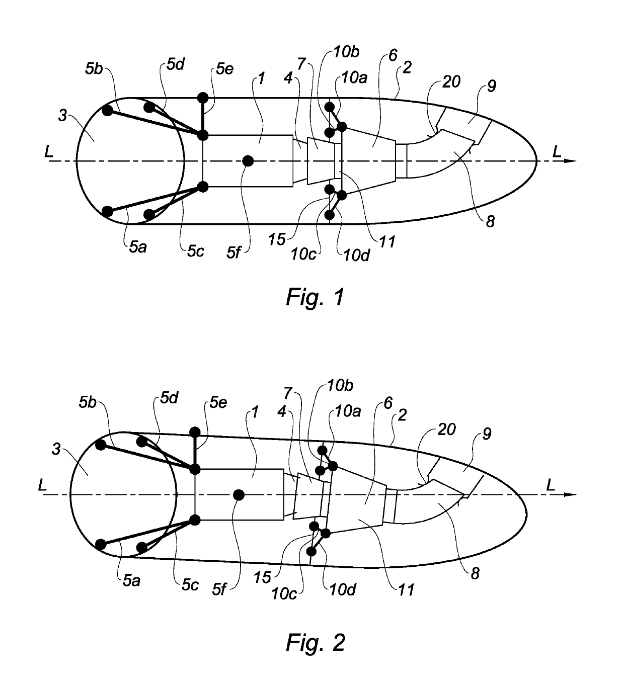
[0031]With reference to FIGS. 1 and 2, the invention relates for example to the installation of an APU engine module 1 in an aircraft compartment that has an elongate shape along a given axis LL and is delimited and at one end along the axis by a shell 2 and closed at the other end by a partition 3 through which this axis passes. The partition 3 and the shell 2 form the structure of the compartment to which equipment can be connected.

[0032]In the case of an APU module installed in a tail cone of an aircraft, for example, the axis LL corresponds to the axis LL of the fuselage that is oriented towards the rear, the partition 3 may be a structural partition of the fuselage, and the shell 2 may comprise the walls of the fuselage downstream of the partition 3 together with the structural elements which support said walls.

[0033]Since, in general, the axis LL is oriented from the front to the rear (from left to right in FIG. 1) and this of course corresponds to the flow direction, for conv...


PUM


Abstract

The invention relates to an assembly comprising a structure (2) and a tubular element (6), which is mounted isostatically in the structure (2), said tubular element (6) comprising a first end (7) connected to said structure by at least four connecting rods 10a-10b-10c-10d, thus setting four first degrees of freedom, and a second end (8) connected to said structure (2) by an attachment means (20) that sets two second degrees of freedom, said connecting rods comprising a means for adjusting the length thereof. In particular, it relates to an exhaust suitable for an auxiliary power unit in the compartment thereof and to the mounting method for aligning them.

Description

FIELD OF THE INVENTION[0001]The present invention relates to the field of the suspension of engines, in particular in an aircraft. It relates more particularly to precisely positioning the engine within the aircraft in relation to equipment that has to cooperate with this engine in order to ensure correct operation.PRIOR ART[0002]In particular, the invention relates to an auxiliary power unit (APU). An APU may provide power to equipment (alternators, pumps, load compressors, air conditioning) of the aircraft, directly and / or indirectly via a power transfer box, in particular during transitional flight phases.[0003]As with any turboshaft engine, an APU conventionally comprises a compressor / combustion chamber / turbine assembly forming a gas generator. Fresh air is introduced into the compressor and then the compressed air, mixed with fuel, causes combustion in the dedicated chamber. The hot gases are expanded in the turbine, which transmits part of the mechanical power supplied to the ...

Claims


Application Information

Patent Timeline
Patent Type & Authority Patents(United States)
IPC IPC(8): G05D1/12B64D41/00B64D33/04B64D33/08
CPCB64D41/00B64D33/04B64D33/08Y02T50/44B64D2041/002Y02T50/40
Inventor CAZENAVE, OLIVIERLALANNE, CLEMENTBARNETO, XAVIER
Owner SAFRAN POWER UNITS
Features
  • R&D
  • Intellectual Property
  • Life Sciences
  • Materials
  • Tech Scout
  • Unparalleled Data Quality
  • Higher Quality Content
  • 60% Fewer Hallucinations
Learn More