
High-transmission-ratio suspension shaft centrifugal supercharger with planetary gear mechanism

a technology of planetary gear mechanism and suspension shaft, which is applied in the direction of gearing, liquid fuel engines, hoisting equipment, etc., can solve the problems of increasing the sliding ratio of a central shaft, unsatisfactory supercharging effect, and increasing noise, so as to improve the power and torque of an engine, improve the transmission precision and the speed increasing ratio, and ensure the effect of long service li

Active Publication Date: 2019-06-04
HUANGSHI XUANYANZHE POWER TECH
View PDF11 Cites 0 Cited by
  • Summary
  • Abstract
  • Description
  • Claims
  • Application Information

AI Technical Summary

Benefits of technology

[0005]In view of the above-mentioned defects in the prior art or improvement demand, it is an objective of the invention to provide a high-transmission-ratio suspension shaft centrifugal supercharger with a planetary gear mechanism, which is capable of improving the power and the torque of an engine and also substantially improving the transmission precision and the speed increasing ratio of the whole machine after the machine operates at a high-speed stage by improving the whole integral construction, the working transmission process and concrete structures and setting ways of multiple key components such as the transmission unit, the friction wheels and the cooling unit, also possesses characteristics of long safe life, convenience to load and install, good heat dispersion, low noise and the like, and accordingly is especially applicable to various small-displacement family cars and agricultural automobiles.

Problems solved by technology

However mechanical supercharging has the disadvantages that supercharging effect is not ideal, noise is relatively large at a high-speed stage, and the like.
However, through engineering application in subsequent several years and actual tests, the centrifugal supercharger still has the following defects or disadvantages: 1) the centrifugal supercharger employs three belt wheels for respectively transmitting engine power to friction wheels as first-order transmission, but once a part of one belt wheel is unstressed during loading, empty load is formed between the belt wheel and the friction wheel, and may cause increase of the sliding ratio of a central shaft and reduction of the transfer efficiency; 2) since a plurality of belt wheels are demanded for executing transmission, the loading orientation is greatly limited when the belt wheels are installed on an automobile engine, and therefore it is difficult to design and install the belt wheels during actual operation; 3) the friction wheel in the centrifugal supercharger, as one of main core components, is composed of a wheel center, a rubber ring, a steel wheel sleeve and a magnetic ring, and a bench test proves that the rubber ring generates difficultly-recovered deformation or even is broken and causes periodic slip between the friction wheel and a center shaft or failure of the whole supercharging system because of high-frequency stress resistance and drawing force after the friction wheel runs for a relatively long period since the rubber bears rotation pressure and circumferential drawing force during rotation in a bench test, which are especially obvious after the rotation speed is improved; and 4) at present a fan is employed for cooling the friction wheel, which is suitable when the transmission efficiency of the supercharger is low or middle, but after the transmission efficiency is improved to a relatively high degree, the cooling effect is limited and is guaranteed only by improving the power of the fan, and accordingly the load of the whole machine is improved and the system noise is substantially increased.

Method used


Image

  • High-transmission-ratio suspension shaft centrifugal supercharger with planetary gear mechanism
  • High-transmission-ratio suspension shaft centrifugal supercharger with planetary gear mechanism

Examples


Embodiment Construction

[0027]For clear understanding of the objectives, technical scheme and advantages of the invention, detailed description of the invention will be given below in conjunction with accompanying drawings and specific embodiments. It should be noted that the embodiments are only meant to explain the invention, and not to limit the scope of the invention. Additionally, technical features referred by embodiments described below may be mutually combined as long as they do not conflict.

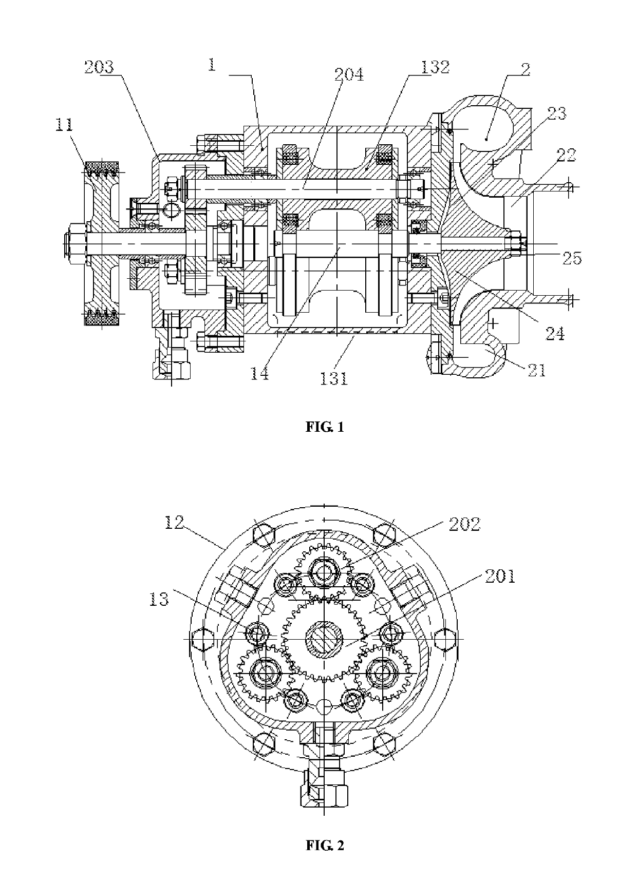
[0028]FIG. 1 illustrates the integral structure and the setting way of a centrifugal supercharger constructed according to the invention. As illustrated in FIG. 1, the centrifugal supercharger mainly comprises a transmission unit 1, a fan supercharging unit 2, a cooling unit 3 and other functional units. Aiming at various disadvantages of conventional mechanical superchargers, the invention performs research design on structures and setting ways of the functional units by referring engineering application pract...


PUM


Abstract

The invention discloses a high-transmission-ratio suspension shaft centrifugal supercharger which comprises a transmission unit, a fan supercharging unit and a cooling unit; the transmission unit is composed of a belt wheel, a planetary gear mechanism, a friction wheel group and a suspension mainshaft, the planetary gear mechanism comprises a sun gear and a planetary gear both installed in a gearbox, the sun gear and the belt wheel are in coaxial installation and rotate together, the planetary gears are distributed at the periphery of the sun gear in a 120 degree symmetric way and are meshed with and follow up the sun gear; the friction wheel group comprises friction wheels arranged in a sealed box and arranged coaxially with corresponding planetary gears; the suspension mainshaft generates contact friction with surfaces of the friction wheels and is driven to rotate together with the friction wheels; the cooling unit is used to pump out high-temperature lubricating oil in the gearbox and the sealed box, and lubricating oil is returned after cooling is performed. According to the invention, the supercharger is substantially improved in transmission precision and speed increasing ratio at a high speed range, and also possesses characteristics of long safe life, convenience for mounting, good heat dispersion performance, low noise and the like.

Description

FIELD OF THE INVENTION[0001]The invention belongs to the technical field of related accessories of explosive motors, and more particularly relates to a high-transmission-ratio suspension shaft centrifugal supercharger with a planetary gear mechanism.BACKGROUND OF THE INVENTION[0002]An explosive motor is usually provided with a supercharger for compressing air before air enters a cylinder so as to improve efficiency and output power, and accordingly more air is sucked for combusting more fuel under the condition of a same cylinder volume, thereby facilitating the purpose of increasing the power.[0003]Conventional engine superchargers in general use employ mechanical supercharging, turbocharging and the like. Mechanical supercharging comprises centrifugal mechanical supercharging, spiral supercharging, Roots supercharging and the like, possesses advantages of work reliability, good linear following feature and excellent performances when an engine operates at a low speed and the like ...

Claims


Application Information

Patent Timeline
Patent Type & Authority Patents(United States)
IPC IPC(8): F02B39/04F16H13/08F04D29/42F04D17/02F16H37/02F16H55/34F16H57/08F16H1/32F16H1/28F04D29/58F04D25/02F02B33/40
CPCF04D29/5806F02B33/40F02B39/04F04D17/025F04D25/028F16H57/08F16H1/28F16H1/32F16H13/08F16H37/02F16H55/34F04D29/4226F16H13/02F16H57/0417F16H57/0441F16H57/0479F16H57/0486F02B39/06
Inventor WANG, ZHIFANGCHEN, TAO
Owner HUANGSHI XUANYANZHE POWER TECH
Features
  • Generate Ideas
  • Intellectual Property
  • Life Sciences
  • Materials
  • Tech Scout
  • Unparalleled Data Quality
  • Higher Quality Content
  • 60% Fewer Hallucinations
Learn More