Data processing system

a data processing and data technology, applied in the field of data processing systems, can solve the problems of high power consumption and limit the recognizable object, and limit the functions of performing augmented reality (ar) display, and achieve the effects of high power consumption, delay in image display, and high convenience of ar display

Active Publication Date: 2019-06-11
SEMICON ENERGY LAB CO LTD
View PDF31 Cites 0 Cited by
  • Summary
  • Abstract
  • Description
  • Claims
  • Application Information

AI Technical Summary

Benefits of technology

[0005]In a method for performing image recognition with a portable terminal by using imaging data, the amount of arithmetic operation increases, resulting in high power consumption and delay in image display.
[0007]An object of one embodiment of the present invention is to provide a novel data processing system capable of highly convenient AR display. Another object of one embodiment of the present invention is to provide a novel data processing system achieving low power consumption. Another object of one embodiment of the present invention is to provide a novel data processing system in which delay in image display is less likely to occur. Another object of one embodiment of the present invention is to provide a novel data processing system in which a privacy issue is less likely to occur. Another object of one embodiment of the present invention is to provide a novel data processing system capable of reducing the amount of data traffic. Another object of one embodiment of the present invention is to provide a novel data processing system.
[0014]One embodiment of the present invention can provide a novel data processing system capable of highly convenient AR display. One embodiment of the present invention can provide a novel data processing system achieving low power consumption. One embodiment of the present invention can provide a novel data processing system in which delay in image display is less likely to occur. One embodiment of the present invention can provide a novel data processing system in which a privacy issue is less likely to occur. One embodiment of the present invention can provide a novel data processing system capable of reducing the amount of data traffic. One embodiment of the present invention can provide a novel data processing system.

Problems solved by technology

In a method for recognizing an object by detecting a maker as in Patent Document 1, there is a limitation on recognizable objects; thus, functions of performing augmented reality (AR) display are limited.
In a method for performing image recognition with a portable terminal by using imaging data, the amount of arithmetic operation increases, resulting in high power consumption and delay in image display.
Moreover, a privacy issue or the like occurs because imaging data including an image of a stranger is sometimes transmitted to the server without being processed.

Method used


Image

  • Data processing system
  • Data processing system
  • Data processing system

Examples


embodiment 1

[0057]A data processing system of one embodiment of the present invention will be described. Note that in this specification and the like, a data processing system refers to a system for storing data applicable to arithmetic processing for realizing augmented reality, virtual reality, or the like in a database connected to a server.

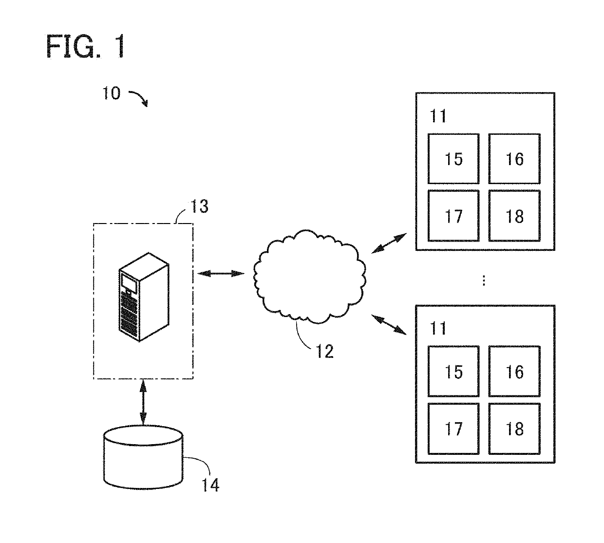
[0058]FIG. 1 illustrates a data processing system 10 of one embodiment of the present invention. The data processing system 10 in FIG. 1 includes portable terminals 11, a network 12, a server 13, and a database 14.

[0059]The portable terminal 11 is an electronic device including a display 15, a position sensor 16, an arithmetic device 17, and an imaging device 18. Note that the portable terminal 11 also includes a plurality of devices such as a communication device and a battery.

[0060]The display 15 is capable of displaying images corresponding to the user's operation, such as an image received from the server 13 and an image based on imaging data obtained...

embodiment 2

[0109]FIG. 10 is a block diagram showing the configuration of a portable terminal in one embodiment of the present invention. For example, the portable terminal 11 includes a CPU 402, a memory 403, a graphics processing unit (GPU) 404, a display controller 405, a display 406, a touch panel controller 407, a touch panel 408, an image sensor controller 409, an image sensor 410, a communication module 411, a power source 442, an input button 413, a position sensor module 414, a direction sensor 415, a photosensor 416, an external memory device controller 417, an audio codec 418, a speaker 419, a microphone 420, an external video input codec 421, and a general-purpose input / output controller 422. The portable terminal 11 may also include a programmable logic device, an analog arithmetic module, or the like that functions as a coprocessor for the CPU 402 or the GPU 404.

[0110]An example of the position sensor module 414 is a GPS for obtaining position information. Examples of the directio...

embodiment 3

[0123]This embodiment will show a structure example of a display including a reflective display element and a light-emitting display element described in Embodiment 2. Specifically, this embodiment will show a structure example of a display including a liquid crystal element as the reflective display element and a light-emitting element with an EL material as the light-emitting display element.

[0124]FIG. 12A illustrates an example of a cross-sectional structure of the display 406 in one embodiment of the present invention. The display 406 in FIG. 12A includes a light-emitting element 203, a liquid crystal element 204, a transistor 205 having a function of controlling supply of a current to the light-emitting element 203, and a transistor 206 having a function of controlling supply of a voltage to the liquid crystal element 204. The light-emitting element 203, the liquid crystal element 204, the transistor 205, and the transistor 206 are positioned between a substrate 201 and a subst...


PUM


Abstract

An object is to provide a novel data processing system. The data processing system includes a portable terminal, a network, a server, and a database. The portable terminal transmits position information to the server through the network. The server transmits, to the portable terminal through the network, a plurality of pieces of object data corresponding to the position information obtained from the database. Imaging data obtained by the portable terminal and the plurality of pieces of object data are compared, and when there is a piece of the object data that does not match the imaging data, the mismatched piece of the object data stored in the database is updated.

Description

BACKGROUND OF THE INVENTION1. Field of the Invention[0001]One embodiment of the present invention relates to a data processing system.2. Description of the Related Art[0002]There has been suggested an image display system that recognizes an object from imaging data obtained by imaging and performs display in combination with a virtual object in a virtual space (see Patent Document 1). In the structure of Patent Document 1, a marker provided in advance is detected from imaging data, and display is performed in combination with a virtual object in a virtual space.PATENT DOCUMENT[0003]Patent Document 1: Japanese Published Patent Application No. 2012-094100SUMMARY OF THE INVENTION[0004]In a method for recognizing an object by detecting a maker as in Patent Document 1, there is a limitation on recognizable objects; thus, functions of performing augmented reality (AR) display are limited.[0005]In a method for performing image recognition with a portable terminal by using imaging data, the...

Claims


Application Information

Patent Timeline
Patent Type & Authority Patents(United States)
IPC IPC(8): G06F17/00G06F16/00G06F1/3234G06F1/3206G09G5/397G06T19/00G06F3/01G06F1/16G01C21/20A63F13/92A63F13/26H04N13/275H04N13/156G01C21/32G06T11/00G06F3/14H04N13/356A63F13/95H04N13/239
CPCG01C21/32A63F13/92G01C21/20G06F1/1616G06F1/3206G06F1/3265G06F3/011G06F3/1423G06F16/00G06T19/006G09G5/397H04N13/156H04N13/275A63F13/26Y02D10/153A63F13/95A63F2300/204G06F2200/1612G06F2200/1637H04N13/356G06F3/14G09G3/20G09G3/3233G09G3/3648G09G2300/023G09G2300/0426G09G2300/046G09G2330/021G09G2340/0407G09G2360/144A63F13/216Y02D10/00H04N13/239
Inventor IKEDA, TAKAYUKI
Owner SEMICON ENERGY LAB CO LTD
Why Eureka
Try Eureka