Gaseous fuel pumping system

a fuel pumping system and gaseous fuel technology, applied in the direction of pumps, fuel supply apparatus, mechanical apparatus, etc., can solve the problems of large power requirement of engine subsystems, large amount of engine energy generated by engines, and other subsystems may be starved of energy

Active Publication Date: 2019-06-18
WESTPORT FUEL SYST CANADA INC
View PDF9 Cites 0 Cited by
  • Summary
  • Abstract
  • Description
  • Claims
  • Application Information

AI Technical Summary

Problems solved by technology

In high horse power applications the amount energy generated by the engine is relatively large and the power requirement for engines subsystems to operate is significant.
When the liquefied gaseous fuel pumping apparatus consumes more than the maximum available electrical power, other subsystems may be starved of energy.
Unlike fuel pumps associated with conventional liquid fuels such as diesel, cryogenic pumps are operated under extreme environmental conditions that result in unique design requirements that tend to increase the size and power consumption of these pumps compared to diesel fuel pumps.
The cryogenic pump consumes more power as the gaseous fuel pressure downstream from the pump increases.
The state of the art is lacking in techniques for supplying an internal combustion engine with gaseous fuel stored in liquefied form.

Method used


Image

  • Gaseous fuel pumping system
  • Gaseous fuel pumping system
  • Gaseous fuel pumping system

Examples


first embodiment

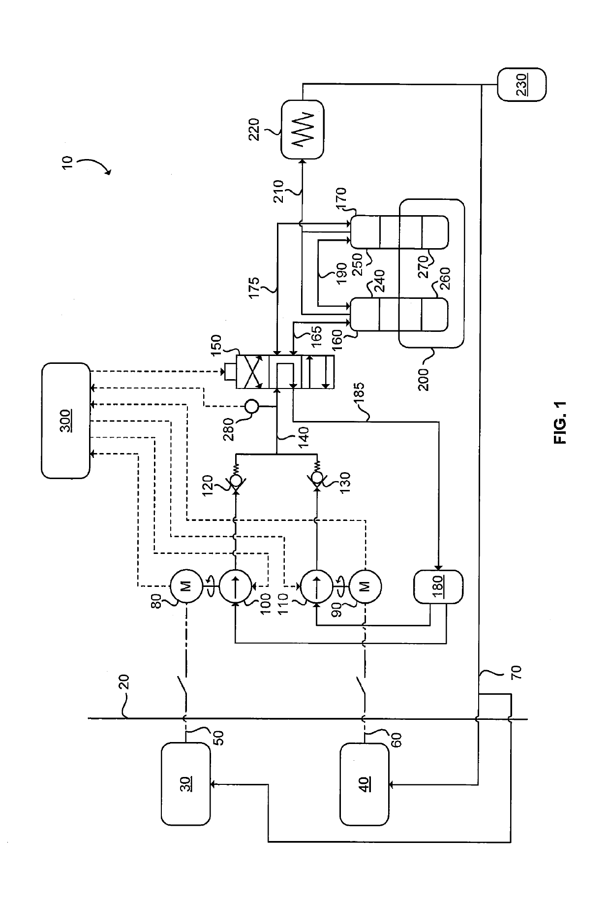
[0025]Referring to FIG. 1, tandem pumping system 10 is a liquefied gaseous fuel pumping system illustrated according to a Demarcation line 20 illustrates the interface between tandem pumping system 10, which in an exemplary embodiment is located on a tender car (not shown), and locomotive engines 30 and 40. The tender car receives electrical power from locomotive engines 30 and 40 over electrical cables 50 and 60 for powering tandem pumping system 10 that supplies pressurized gaseous fuel to the locomotives over conduit 70. Depending on the location of the locomotives relative to the tender car conduit 70 can branch out of various locations on the tender car or on one of these locomotives. The electrical power drives electric motors 80 and 90, which in turn drive respective variable displacement hydraulic pumps 100 and 110, which in an exemplary embodiment are swash-plate pumps. The hydraulic flow from hydraulic pumps 100 and 110 is combined after check valves 120 and 130, which ar...

third embodiment

[0031]Referring now to FIG. 5, tandem pumping system 13 is illustrated according to a Motor driver 330 combines the AC electrical signals received from engines 30 and 40 and is commanded by electronic controller 300 to generate a drive signal for electric motor 83. Hydraulic pump 103 can be a variable displacement pump, as in the embodiment of FIG. 1, or fixed displacement pump as in the embodiment of FIG. 4. The hydraulic flow can be controlled by adjusting the drive signal supplied to motor 83, and / or by adjusting the swash-plate angle of pump 103. In those embodiments that employ a variable displacement pump, such as a swash plate pump, the hydraulic flow can be adjusted by varying both the swash-plate angle and the speed (rpm) at which the swash plate pump operates. Motor driver 330 electrically isolates the AC electrical power from engines 30 and 40, such as by employing electrical transformers. The drive signal from motor driver 330 can be an AC electrical signal when electri...


PUM


Abstract

In high horse power engines there are strict energy budgets allotted for each subsystem. It is a challenge for a gaseous fuel pumping system to supply the necessary gaseous fuel mass flow to the engine while staying within budget. A method for pressurizing a gaseous fuel supplied to an engine comprises providing first and second hydraulically actuated pumping apparatus comprising first and second shuttle valves in first and second hydraulic pistons respectively; and selectively communicating hydraulic fluid flow to the first and second hydraulically actuated pumping apparatuses. In a first mode hydraulic fluid is communicated through the first hydraulically actuated pumping apparatus to the second hydraulically actuated pumping apparatus. In a second mode hydraulic fluid is communicated through the second hydraulically actuated pumping apparatus to the first hydraulically actuated pumping apparatus. The method switches between the first and second modes when a pressure drop in hydraulic fluid pressure associated with the hydraulic fluid flowing through the first and second shuttle valves is detected.

Description

FIELD OF THE INVENTION[0001]The present application relates to a gaseous fuel pumping system for pressurizing a gaseous fuel in a resource constrained environment.BACKGROUND OF THE INVENTION[0002]Internal combustion engines supplying motive power to a vehicle generate power not only for propulsion, but also to operate various systems associated with the engine. For example, a fuel pump can be mechanically driven from a power take-off on the engine, or can be electrically driven from a battery that is supplied electrical power from an alternator driven by the engine. In both circumstances, the engine provides power to drive the fuel pump. Over the range of engine operating conditions the engine supplies sufficient power to the fuel pump to meet the fuel demand of the engine.[0003]In all applications there is a finite source of power available from the engine for subsystems to operate without significantly affecting engine efficiency. Continuous improvement in these subsystems reduces...

Claims


Application Information

Patent Timeline
Patent Type & Authority Patents(United States)
IPC IPC(8): F04B9/08F02D19/02F02D25/00F02M21/02F04B49/03F04B49/06
CPCF02D19/022F02D25/00F02M21/0245F02M21/0287F04B9/08F04B49/03F04B49/06Y02T10/32Y02T10/30
Inventor EBBEHOJ, MICHAELKRATSCHMAR, KENNETH W.
Owner WESTPORT FUEL SYST CANADA INC
Why Eureka
Try Eureka