Detecting location within a network

a wireless communication network and location technology, applied in the field of object detection, can solve the problems of reducing accuracy, general less effective indoors, and prone to signal noise of radar signals, so as to improve the accuracy of the system over time, and improve the ability of location calculation

Active Publication Date: 2019-06-18
IVANI
View PDF187 Cites 0 Cited by
  • Summary
  • Abstract
  • Description
  • Claims
  • Application Information

AI Technical Summary

Benefits of technology

[0026]In another embodiment of the method, the determination whether a human is present within the detection area is adjusted based on machine learning comprising: determining based on user input or action that a human was present in an area when the sample signal properties correspond at least in part with baseline signal properties of an empty space, modifying, at least in part, the baseline signal properties for an empty space; modifying, at least in part, the signal properties associated with an occupied space; and adjusting the method for comparing sample signal properties to the baseline and other comparative signal properties to improve the accuracy of the system over time.
[0032]In another embodiment of the method, the determination to operate the first external system and the determination not to operate the second external system is adjusted based on machine learning comprising: determining a first sample location of a human in the detection area using inference, the first sample location being determined based upon detecting the human interacting with the system in some known way; determining a second sample location of the human in the detection area, the second sample location being determined based at least in part on a comparison of the received second set of signal data to the baseline signal profile not utilizing the inferred location; comparing the first sample location and the second sample location; and adjusting the determination steps based on inferred location to improve the location calculating capabilities of the system, the adjusting based upon the comparing step.

Problems solved by technology

However, such systems are generally less effective indoors, where satellite signals may be blocked, reducing accuracy.
These systems have several disadvantages, among them that the object tracked must include a transceiver.
For example, radar signals are susceptible to signal noise, or random variations in the signal caused by internal electrical components, as well as noise and interference from external sources, such as the natural background radiation.
Radar is also vulnerable to external interference sources, such as intervening objects blocking the beam path and can be deceived by objects of particular size, shape, and orientation.

Method used


Image

  • Detecting location within a network
  • Detecting location within a network
  • Detecting location within a network

Examples


Embodiment Construction

)

[0046]The following detailed description and disclosure illustrates by way of example and not by way of limitation. This description will clearly enable one skilled in the art to make and use the disclosed systems and methods, and describes several embodiments, adaptations, variations, alternatives and uses of the disclosed systems and methods. As various changes could be made in the above constructions without departing from the scope of the disclosures, it is intended that all matter contained in the description or shown in the accompanying drawings shall be interpreted as illustrative and not in a limiting sense.

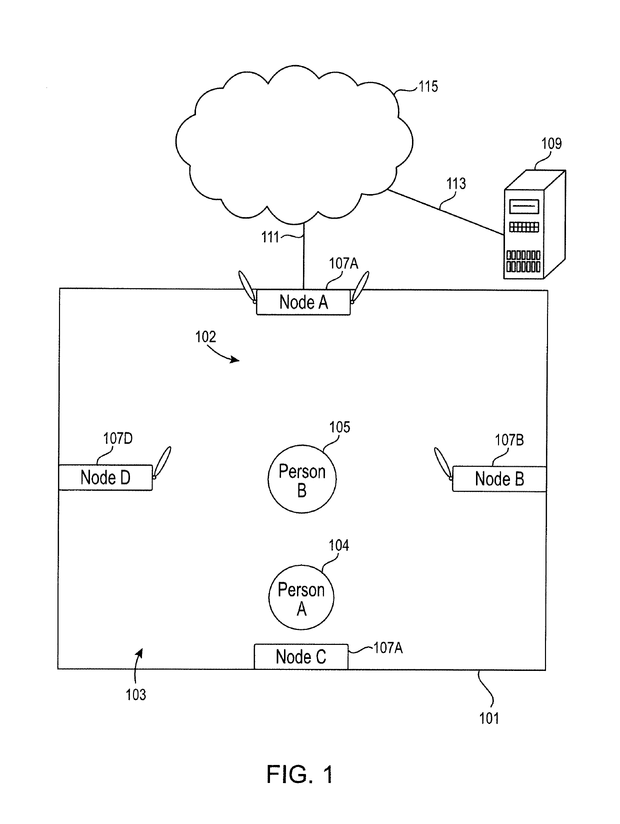
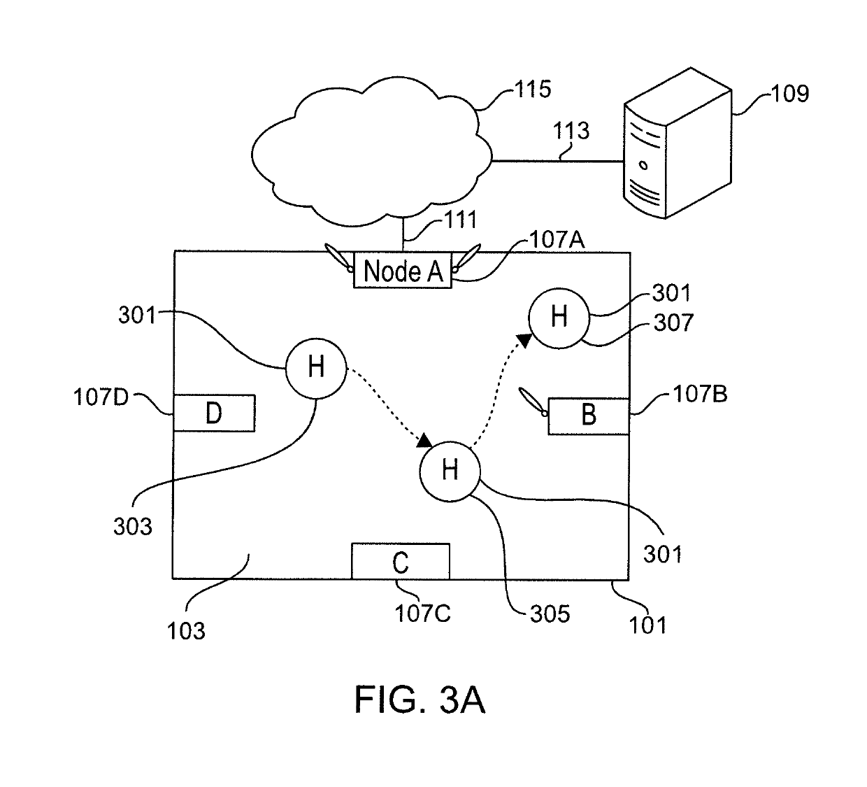
[0047]Generally speaking, described herein, among other things, are systems and methods for detecting the presence of a body in a network without fiducial elements. Generally speaking, the systems and methods described herein use signal absorption, and signal forward scatter and reflected backscatter of the RF communication caused by the presence of a biological mass in ...


PUM


Abstract

Systems and methods for detecting the presence of a body in a network without fiducial elements, using signal absorption, and signal forward and reflected backscatter of radio frequency (RF) waves caused by the presence of a biological mass in a communications network.

Description

CROSS-REFERENCE TO RELATED APPLICATIONS[0001]This application is a continuation of Ser. No. 15 / 674,328, filed Aug. 10, 2017, which is a continuation-in-part of U.S. Utility patent application Ser. No. 15 / 600,380, filed May 19, 2017, which is a continuation of U.S. Utility patent application Ser. No. 15 / 227,717, filed Aug. 3, 2016, and issued on Jun. 27, 2017, as U.S. Pat. No. 9,693,195, which claims the benefit of U.S. Provisional Patent Application No. 62 / 252,954, filed Nov. 9, 2015, and U.S. Provisional Patent Application No. 62 / 219,457, filed Sep. 16, 2015 and which is a continuation of U.S. Utility patent application Ser. No. 15 / 084,002, filed Mar. 29, 2016, and issued on Oct. 18, 2016, as U.S. Pat. No. 9,474,042, which applications in turn also claim benefit of the above-referenced provisional applications. The entire disclosure of all of these documents is herein incorporated by reference.BACKGROUND1. Field of the Invention[0002]This disclosure is related to the field of objec...

Claims


Application Information

Patent Timeline
Patent Type & Authority Patents(United States)
IPC IPC(8): H04M11/04G11C11/22
CPCG11C11/2257G11C11/2259G11C11/2273G11C11/2293G11C11/2297G11C11/221G11C11/2255G11C11/2275G11C11/5657
Inventor WOOTTON, JOHNWOOTTON, MATTHEWNISSMAN, CHRISPRESTON, VICTORIACLARK, JONATHANMCKINNEY, JUSTINBARNES, CLAIREXIAO, XINYUWANG, ZHECAN
Owner IVANI
Why Eureka
Try Eureka