
Imprint apparatus, method of manufacturing article, and supply apparatus

a technology of imprinting apparatus and supply apparatus, which is applied in the direction of photomechanical treatment, material nanotechnology, instruments, etc., can solve the problems of affecting the yield, the imprint material may be contaminated, and the imprint material itself cannot be contaminated, so as to prevent or reduce the contamination of the imprint material

Active Publication Date: 2019-06-25
CANON KK
View PDF28 Cites 0 Cited by
  • Summary
  • Abstract
  • Description
  • Claims
  • Application Information

AI Technical Summary

Benefits of technology

The invention provides an imprint machine that can stop or reduce contamination of the ink used for printing.

Problems solved by technology

The imprint material may be contaminated by a foreign substance or a metal in a process using the imprint material.
If the contaminated imprint material is used, a defective pattern is formed on the substrate, affecting a yield.
In this related art, however, it is impossible to prevent the contamination itself of an imprint material while it is possible to deal with an imprint material that has already been contaminated.
In this case, replacement of the imprint material itself is unavoidable.
It is extremely difficult to remove all contaminants that have entered an imprint material.
It is difficult to supply the imprint material stably and ensure a yield unless the contamination itself of the imprint material can be prevented.
Inside the tank, the amount of the imprint material changes by discharging the imprint material, causing a pressure fluctuation.
That is, the imprint material stored in the tank may be contaminated.

Method used


Image

  • Imprint apparatus, method of manufacturing article, and supply apparatus
  • Imprint apparatus, method of manufacturing article, and supply apparatus
  • Imprint apparatus, method of manufacturing article, and supply apparatus

Examples


Embodiment Construction

[0015]Preferred embodiments of the present invention will be described below with reference to the accompanying drawings. Note that the same reference numerals denote the same members throughout the drawings, and a repetitive description thereof will not be given.

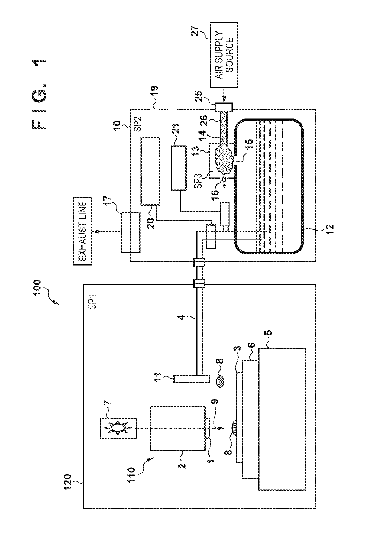
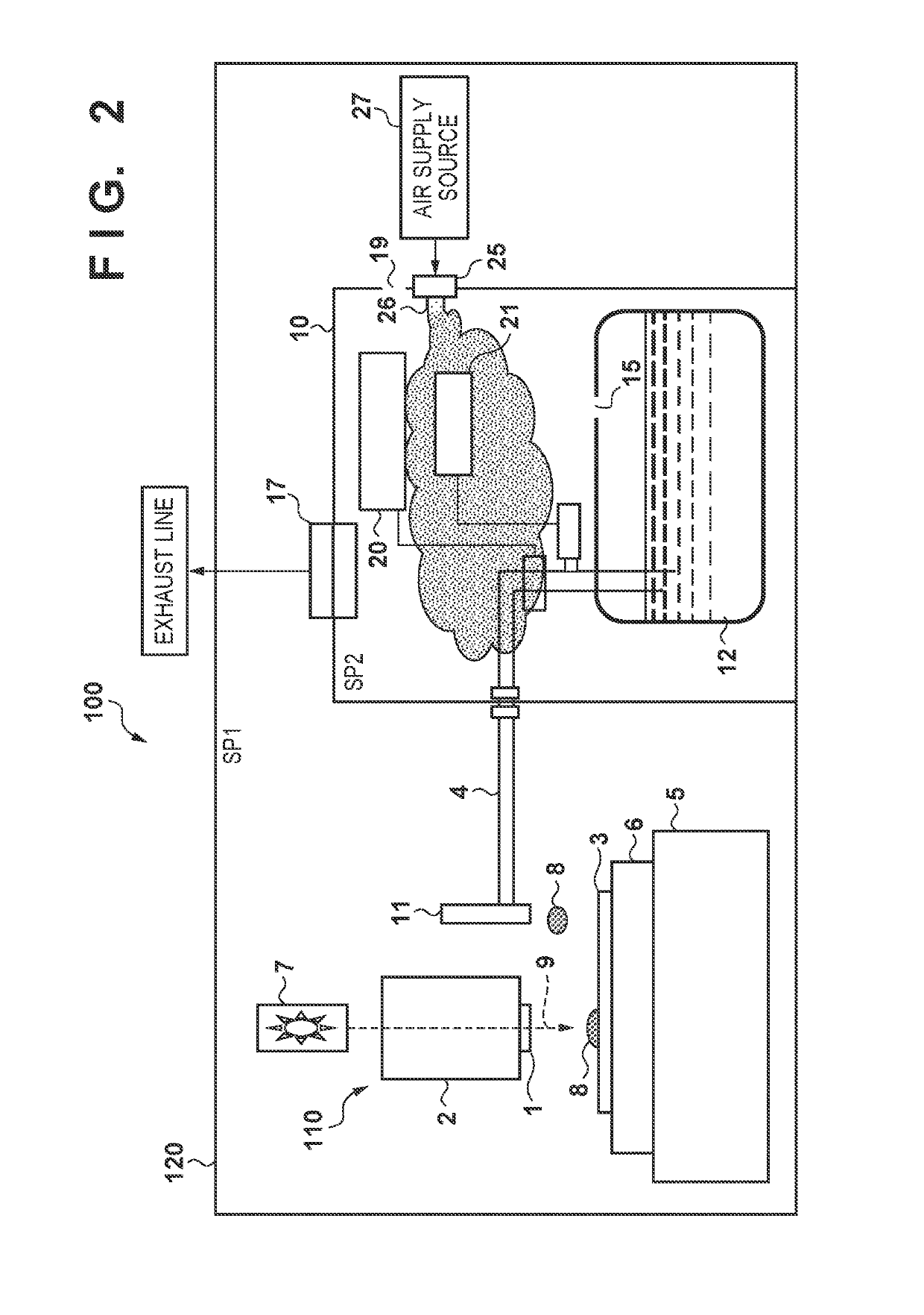
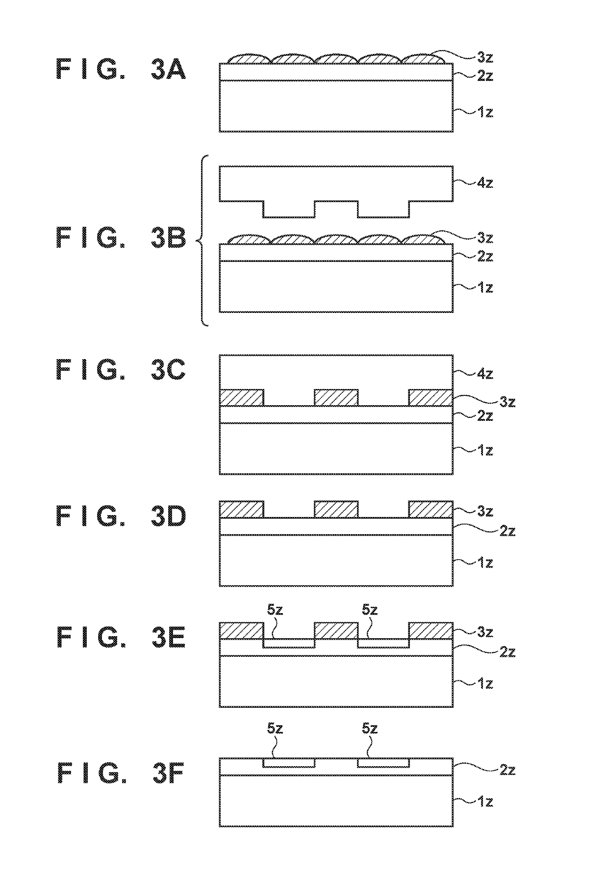
[0016]FIG. 1 is a schematic view showing the arrangement of an imprint apparatus 100 according to an aspect of the present invention. The imprint apparatus 100 is a lithography apparatus which forms a pattern on a substrate by curing an imprint material on the substrate in a state in which a mold and the imprint material are in contact with each other, and releasing the mold from the cured imprint material.

[0017]Glass, ceramics, a metal, a semiconductor, a resin, or the like is used for the substrate. A member made of a material different from that of the substrate may be formed on the surface of the substrate, as needed. More specifically, a silicon wafer, a compound semiconductor wafer, silica glass, or the like is used a...


PUM

PropertyMeasurementUnit
wavelengthaaaaaaaaaa
pressureaaaaaaaaaa
atmospheric pressureaaaaaaaaaa

Abstract

The present invention provides an imprint apparatus including a chamber configured to define a first space including a processing unit which includes a discharge unit configured to discharge an imprint material onto a substrate and is configured to perform an imprint process of forming a pattern of the imprint material on the substrate by using a mold, and an enclosure configured to define a second space including a tank configured to store the imprint material supplied to the discharge unit, wherein the tank has a first opening open to the second space, and the enclosure has a supply port configured to supply, to the second space via the first opening, a gas cleaner than a gas supplied to the first space.

Description

BACKGROUND OF THE INVENTION[0001]Field of the Invention[0002]The present invention relates to an imprint apparatus, a method of manufacturing an article, and a supply apparatus.[0003]Description of the Related Art[0004]As demands for micropatterning semiconductor devices increase, a microfabrication technique of molding an uncured imprint material (resin material) on a substrate with a mold and forming a pattern of the imprint material on the substrate is attracting attention, in addition to the conventional photolithography technique. This technique is also called an imprint technique and can form a fine structure of several nm order on the substrate.[0005]A photo-curing method is one example of the imprint technique. In an imprint apparatus which adopts the photo-curing method, first, an imprint material is supplied (applied) to a shot region (imprint region) on a substrate. Then, an uncured imprint material on the substrate is cured by irradiating it with light in a state in whic...

Claims


Application Information

Patent Timeline
Patent Type & Authority Patents(United States)
IPC IPC(8): B29C70/78H01L21/027G03F7/00
CPCG03F7/0002B82Y30/00B82Y40/00G03F7/168G03F7/3071G03F7/70858
Inventor ASADA, KUNIHIKOARAI, TSUYOSHI
Owner CANON KK
Learn More