Non-lubricated architecture for a turboshaft engine

Active Publication Date: 2019-07-02
SAFRAN HELICOPTER ENGINES
View PDF35 Cites 2 Cited by
  • Summary
  • Abstract
  • Description
  • Claims
  • Application Information

AI Technical Summary

Benefits of technology

The present invention provides a turbine engine architecture for a helicopter that reduces the size of the lubrication system. The engine does not have a speed reducer or an accessory box, and the speed reducer is located within the main gearbox of the helicopter. The gearing of the speed reducer is lubricated within the MGB, eliminating the need for oil lubrication within the engine. The engine casing and the main gearbox are sealed to prevent lubrication oil from leaking out of the main gearbox. This results in an oil-free architecture for the turboshaft engine, improving its performance and reliability.

Problems solved by technology

In particular, it constitutes a source of leaks that can be troublesome for operators, and that requires the pilot to verify oil level.
Finally, the lubrication system is heavy, expensive, and usually polluting.

Method used


Image

  • Non-lubricated architecture for a turboshaft engine
  • Non-lubricated architecture for a turboshaft engine
  • Non-lubricated architecture for a turboshaft engine

Examples


Embodiment Construction

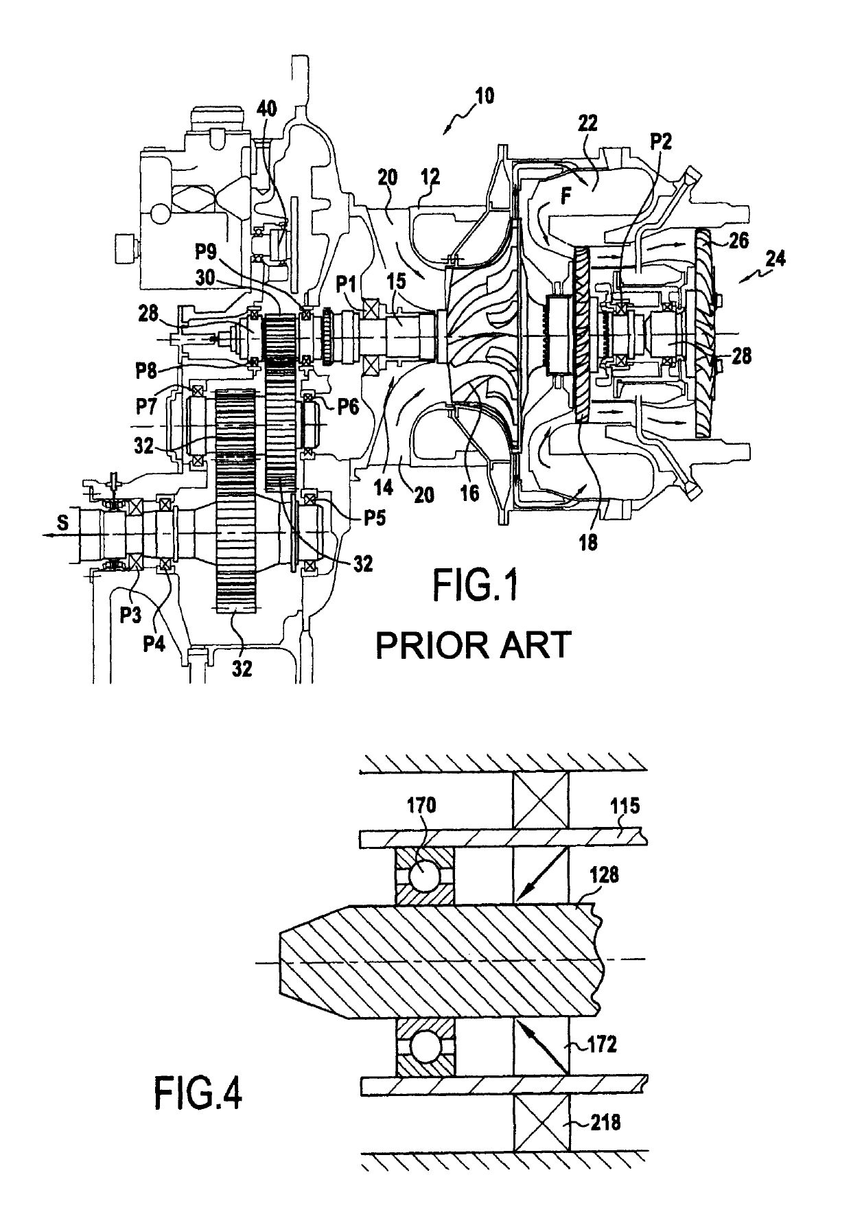
[0040]FIG. 1 is a longitudinal section view of a prior art helicopter turboshaft engine 10. That turboshaft engine 10 comprises a casing 12 housing a gas generator 14. The gas generator has a gas generator shaft 15 carrying a centrifugal compressor wheel 16 and a high pressure turbine 18. Fresh air penetrates into the turboshaft engine via an air inlet 20. It is then compressed by the compressor 16 prior to being sent into a combustion chamber 22 where it is mixed with fuel. The combustion of the mixture of compressed air and fuel generates a gas stream F that drives the high pressure turbine 18 in rotation, which in turn drives the compressor 16. The gas generator is carried by bearings P1 and P2 that provide rotary guidance and that also take up the forces to which the gas generator 15 is subjected. Those bearings are lubricated with oil by means of a lubrication system (not shown). Furthermore, the turboshaft engine also has a free turbine 24 with a low pressure turbine wheel 26 ...


PUM


Abstract

A turbine engine for a helicopter, the helicopter including a main gearbox, a rotor, and a speed-reducing device housed entirely within the main gearbox of the helicopter while also being connected to the rotor, the turbine engine including a casing, a gas generator with a gas generator shaft, and a free turbine for being driven in rotation by a gas stream generated by the gas generator, the free turbine including a free turbine shaft. When the turbine engine is fastened to the gearbox of the helicopter, the free turbine shaft extends axially into the main gearbox of the helicopter to be connected directly to the speed-reducing device.

Description

BACKGROUND OF THE INVENTIONField of the Invention[0001]The present invention relates to the field of gas turbines and in particular to that of turboshaft engines for flying machines such as helicopters.[0002]The present invention relates more particularly to a turboshaft engine, in particular for a helicopter, having a gas generator and a free turbine driven in rotation by the stream of gas generated by the gas generator.Description of the Related Art[0003]Traditionally, the gas generator comprises at least a compressor and a turbine that are coupled to rotate together. The principle of operation is as follows: fresh air entering into the engine is compressed as a result of the compressor rotating, prior to being delivered to a combustion chamber where it is mixed with fuel. The gas burnt resulting from the combustion is then exhausted at high speed.[0004]First expansion then takes place in the turbine of the gas generator, during which expansion the turbine extracts the energy need...

Claims


Application Information

Patent Timeline
IPC IPC(8): B64C27/14F02C3/10F02C7/06F01D25/22B64C27/12F02C7/36
CPCB64C27/12F01D25/22F02C3/103F02C7/06F02C7/36Y02T50/671F05D2220/76F05D2240/51F05D2240/52F05D2240/54F05D2220/329Y02T50/60
Inventor BEDRINE, OLIVIERPATY, GERARD
Owner SAFRAN HELICOPTER ENGINES
Why Eureka
Try Eureka