Electric-motor-driven liquid pump

a technology of electric motors and liquid pumps, which is applied in the direction of liquid fuel engines, electrical apparatus, dynamo-electric machines, etc., can solve the problems of limiting the use of such a pump in small spaces, the need to ensure reliable pump operation, and the inability to adequately dissipate heat generated by electronic power units, so as to achieve the effect of low production costs

Active Publication Date: 2019-07-02
FTE AUTOMOTIVE GMBH & CO KG
View PDF18 Cites 8 Cited by
  • Summary
  • Abstract
  • Description
  • Claims
  • Application Information

AI Technical Summary

Benefits of technology

[0008]In the liquid pump according to one aspect of the invention the liquid is thus advantageously used on the suction side of the conveying device for cooling purposes. This is more efficient by comparison with similar prior solutions in which a part of the conveyed liquid is branched off on the pressure side of the conveying device for pump cooling. This is because, firstly, the liquid conveyed by the conveying pump can at the pressure side be delivered in its entirety by way of the pressure connection—thus there is no dividing up for cooling purposes. Secondly, the liquid, for example transmission oil, “heated up” at the suction side of the conveying device by way of the electric motor and the electronic power unit can be more easily conveyed because the internal friction in the liquid is less due to the temperature-induced change in viscosity.
[0021]Finally, in principle, various types of pumps can be used as the conveying device: thus, the conveying device of the liquid pump according to the invention can be constructed in the manner of, for example, a piston pump, a vane pump, a roller pump, a centrifugal pump or any form of gear pump. For a relatively low pressure range an embodiment of the liquid pump is preferred, particularly with respect to low production costs, in which the conveying device is constructed in the form of an internal gear pump, comprising a gearwheel, which is rotationally driven by the rotor of the electric motor and is arranged concentrically with respect to the axis of rotation, with an outer toothing and an annular gear, which meshes with the outer toothing and is guided eccentrically in the housing with respect to the axis of rotation, with an inner toothing which co-operates with the outer toothing so as to convey liquid. Such a conveying device accordingly needs merely two, optionally sintered, rotor parts (gearwheel and annular gear).

Problems solved by technology

On the one hand, the available installation space within or in the vicinity of the transmission housing is usually very meager in size, so that the pump has to be constructed as compactly as possible.
These requirements are mutually contradictory: the more compact the construction of the pump for a given pump output, for example pressures up to 30 bars or volume flows up to 25 liters per minute in transmission applications, has to be the more difficult it can be to ensure reliable functioning of the pump over a large temperature range.
In that case, in the low temperature range the high viscosity of the oil in conjunction with small flow cross-sections, in particular, can prove problematic, whereas at high temperatures the primary challenge is adequate heat dissipation from the electric motor.
However, care still has to be given to adequate dissipation of the heat generated by the electronic power unit.
Moreover, in this construction there is a significant axial installation space requirement, which limits the possibilities of use of such a pump in small spaces.

Method used


Image

  • Electric-motor-driven liquid pump
  • Electric-motor-driven liquid pump
  • Electric-motor-driven liquid pump

Examples


Embodiment Construction

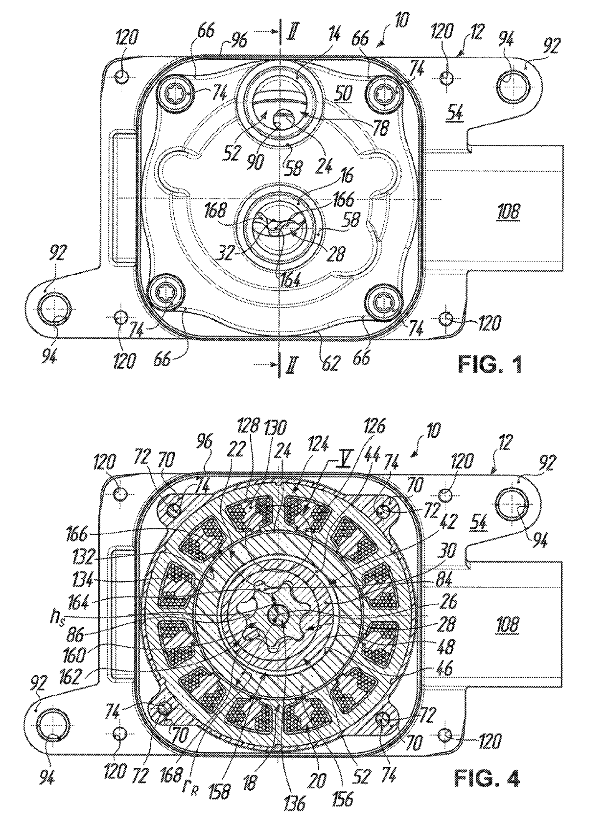
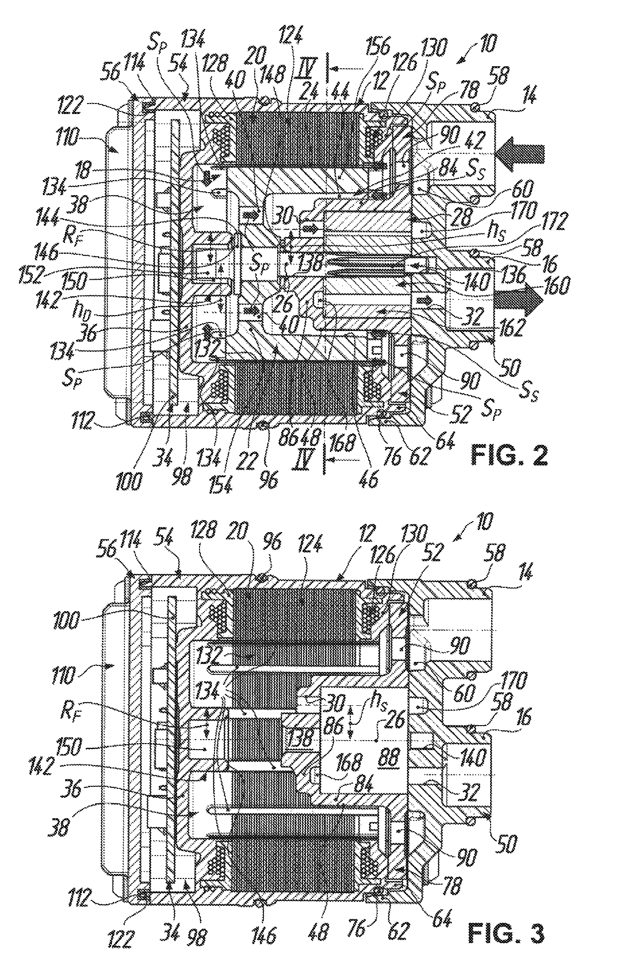
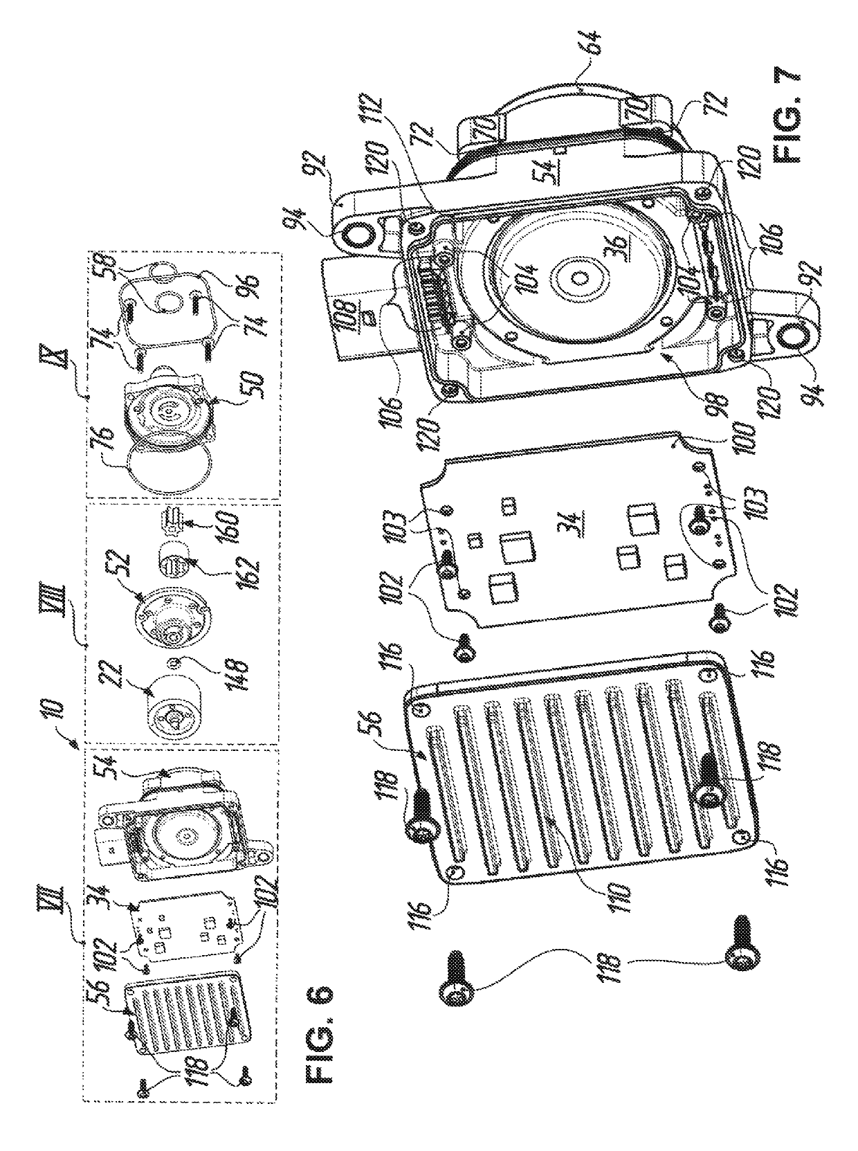
[0032]In the figures the reference numeral 10 denotes generally an electric-motor-driven liquid pump which can be used in or at a transmission for motor vehicles, particularly as an oil pump for cooling and / or lubricating purposes. The liquid pump 10 has a housing which is denoted generally by 12 and which has a suction connection 14 and a pressure connection 16. As FIG. 2, in particular shows an electric motor 18 is arranged in the housing 12 and includes a stator 20 at the housing and an internal rotor 22. The rotor 22 is received within the stator 20 so as to leave an annular gap 24 and is rotationally drivable about an axis 26 of rotation. A conveying device which is denoted generally by 28 in FIGS. 2 and 4 and which has a suction inlet 30 in fluid connection with the suction connection 14 of the housing 12 and a pressure outlet 32 in fluid connection with the pressure connection 16 of the housing 12 is drivably connected with the rotor 22 of the electric motor 18. In addition, ...


PUM


Abstract

A liquid pump has a housing with a suction connection, a pressure connection and a electric motor for rotationally driving a conveying device that has a suction inlet and pressure outlet which communicate with the suction connection and the pressure connection respectively. An electronic power unit for the electric motor is adjacent to the motor and extends transversely to the axis of rotation and is on the rear side of the partition wall of the housing. The suction inlet is arranged at a height smaller than an inner radius of an annular gap between the stator and rotor, whereas a rotor passage extends at a constant height, so that a liquid inducted by way of the suction connection is guided in part via the annular gap and undergoes a deflection at the partition wall, cooling the latter before it passes through the rotor passage to the suction inlet.

Description

TECHNICAL FIELD[0001]The present invention relates to electric-motor-driven liquid pumps made predominantly from plastic material components to be used on a large scale in the automobile industry as, for example, lubricating oil pumps, cooling oil pumps, auxiliary oil pumps or actuator pumps so as to contribute, by virtue of their low weight and their capability to have electrical drive control that is regulated to need, to a reduction in fuel consumption and CO2 emissions.PRIOR ART[0002]Low emission of pollutants and lowest possible fuel consumption during operation of a motor vehicle have, as has become known, an important role in the development of new vehicles and vehicle concepts; these aspects will be even more in the focus of developers in the future, also due to legal regulations. Given this objective, regulable electrical oil pumps can be variously used in the area of the drive train of a motor vehicle, particularly within the transmission and also in the transmission spher...

Claims


Application Information

Patent Timeline
Patent Type & Authority Patents(United States)
IPC IPC(8): F04C15/00F04B53/08F04D1/04F04B17/03F04D29/58F04D13/06F04C2/10
CPCF04C15/0096F04B17/03F04B53/08F04C2/102F04D29/5813F04D13/06F04D13/0653F04D29/586F04D29/5806F04D1/04F04C2/10F04C11/008H02K9/19F04C15/008F04C2240/30F04C2240/40F04C2210/20F05B2210/11
Inventor REUL, ALEXANDERDIRAUF, MARKUS
Owner FTE AUTOMOTIVE GMBH & CO KG
Why Eureka
Try Eureka