Folder for rotary press

a rotary press and folding technology, applied in the field of folding machines, can solve the problems of reduced folding accuracy, machine shutdown, and difficulty in ensuring sufficient folding accuracy, and achieve the effects of improving printing quality, high degree of accuracy, and accurately processing

Inactive Publication Date: 2007-01-25
MITSUBISHI HEAVY IND PRINTING & PACKAGING MACHINERY
View PDF14 Cites 10 Cited by
  • Summary
  • Abstract
  • Description
  • Claims
  • Application Information

AI Technical Summary

Benefits of technology

[0042] According to the folding machine (and the variable cut-off length type rotary printing machine) of the disclosed embodiment, a sheet is cut off by the cut-off unit from a web fed from the printing unit of a rotary printing machine and is conveyed to a downstream processor by first and second belt conveyors and processed. In the printing unit and cut-off unit, the web is conveyed at a fixed speed and printing and cutting are performed. The cut-off sheet is conveyed by the first belt conveyor and is further delivered to the second belt conveyor. The second belt conveyor varies a sheet conveying speed during the conveyance of the sheet so that in receiving the sheet from the first belt conveyor, the sheet conveying speed becomes approximately equal to a first speed at which the sheet is conveyed in the first belt conveyor, and in conveying the sheet to the processor, the sheet conveying speed becomes approximately equal to a second speed at which the sheet is conveyed in the processor. Therefore, the sheet cut off by the cut-off unit is delivered at an equal speed when delivering the sheet from the first belt conveyor to the second belt conveyor and when delivering the sheet from the second belt conveyor to the processor. As a result, sheets cut off from the web can be processed with a high degree of accuracy.
[0043] Particularly, in a rotary printing machine (variable cut-off length type rotary printing machine) constructed such that it can vary and cut a cut-off length of a web fed from the printing unit, if a speed at which the web is conveyed is set according to a cut-off length of a sheet that is cut off by the cut-off unit, and the first speed at which the sheet is conveyed in the first belt conveyor is set so that it becomes equal to the web conveying speed, the cut-off length of the web can be properly varied. In addition, as set forth above, the second belt conveyor varies a sheet conveying speed during the conveyance of the sheet so that in receiving the sheet from the first belt conveyor, the sheet conveying speed becomes approximately equal to a first speed at which the sheet is conveyed in the first belt conveyor, and in conveying the sheet to the processor, the sheet conveying speed becomes approximately equal to a second speed at which the sheet is conveyed in the processor. Therefore, the sheet cut off by the cut-off unit is delivered at an equal speed when delivering the sheet from the first belt conveyor to the second belt conveyor and when delivering the sheet from the second belt conveyor to the processor. Thus, a sheet can be cut to a predetermined cut-off length and the cut-off sheet can be accurately processed. This contributes to an enhancement in print quality.
[0044] Furthermore, the aforementioned cut-off unit may be constructed such that it includes a first cut-off mechanism for partially cutting a web and a second cut-off mechanism, provided downstream of the first cut-off mechanism, for cutting off a sheet from the web by cutting uncut portions of the web other than the portions cut by the first cut-off mechanism. In this case, in the cut-off unit, the web is partially cut at a predetermined cut-off length position by the first cut-off mechanism. Thereafter, while this web is being nipped and conveyed by the first belt conveyor, a sheet with a predetermined cut-off length is cut off by cutting uncut portions of the web with the second cut-off mechanism. Therefore, cutting of the web can be performed in a stable state of conveyance and the cut-off sheets can be easily conveyed at the required phase timing. As a result, cutting of the web and processing of cut-off sheets can be performed with a high degree of accuracy.
[0045] In this case, if the aforementioned first belt conveyor nips the web that is cut by the second cut-off mechanism, and the folding machine further includes a fourth belt conveyor comprising a pair of conveyor belts for nipping and conveying the web to the first cut-off mechanism, the web can be stably and accurately cut by the first cut-off mechanism.
[0046] It is preferable that a first relative-phase changer be interposed between the first cut-off mechanism and the second cut-off mechanism, for changing relative phases of rotation of the first cut-off mechanism and the second cut-off mechanism when varying a cut-off length of the web fed from the printing unit.
[0047] It is preferable that a scored-line forming mechanism be provided upstream of the first and second cut-off mechanisms, for forming a horizontally scored line in the web at a predetermined position, and it is also preferable that a second relative-phase changer be interposed between the scored-line forming mechanism and the first cut-off mechanism, for changing relative phases of rotation of the scored-line forming mechanism and the first cut-off mechanism when varying a cut-off length of the web fed from the printing unit.

Problems solved by technology

This can cause a shift in the timing at which the sheet 10a is delivered from the variable speed belt conveyor 30 to the catching-folding unit40B, so it is fairly difficult to ensure sufficient accuracy of folding (accuracy of folding position or folding phase).
Particularly, cumulation of the aforementioned shifts in the timing can cause not only a reduction in accuracy of folding but also incomplete delivery between the accelerating belt convey or 30 and the catching-folding unit 40B, so that there are cases where the folding machine has to be shut down.

Method used


Image

  • Folder for rotary press
  • Folder for rotary press
  • Folder for rotary press

Examples


first embodiment

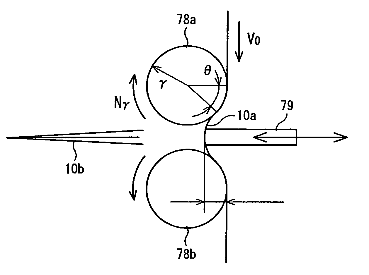
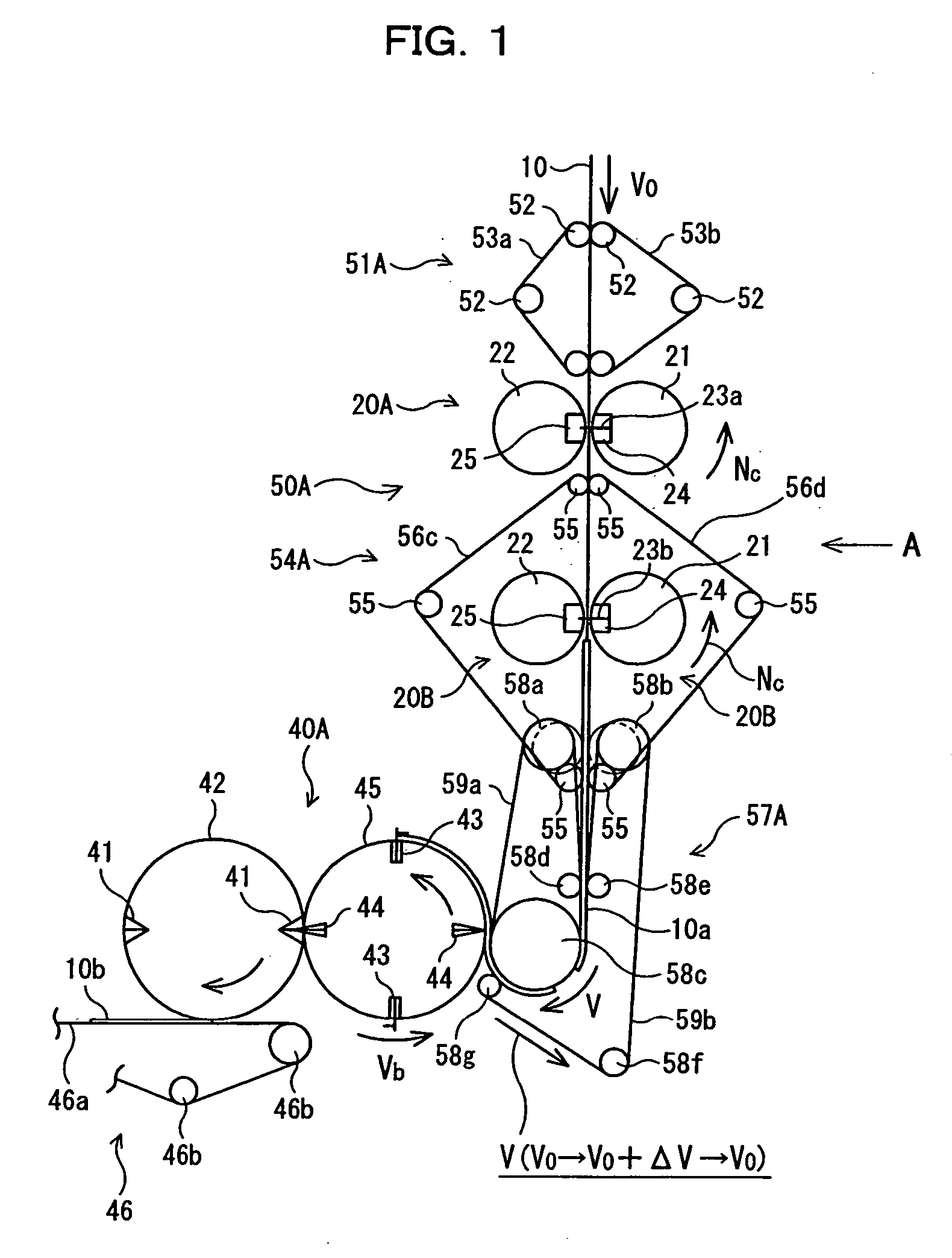
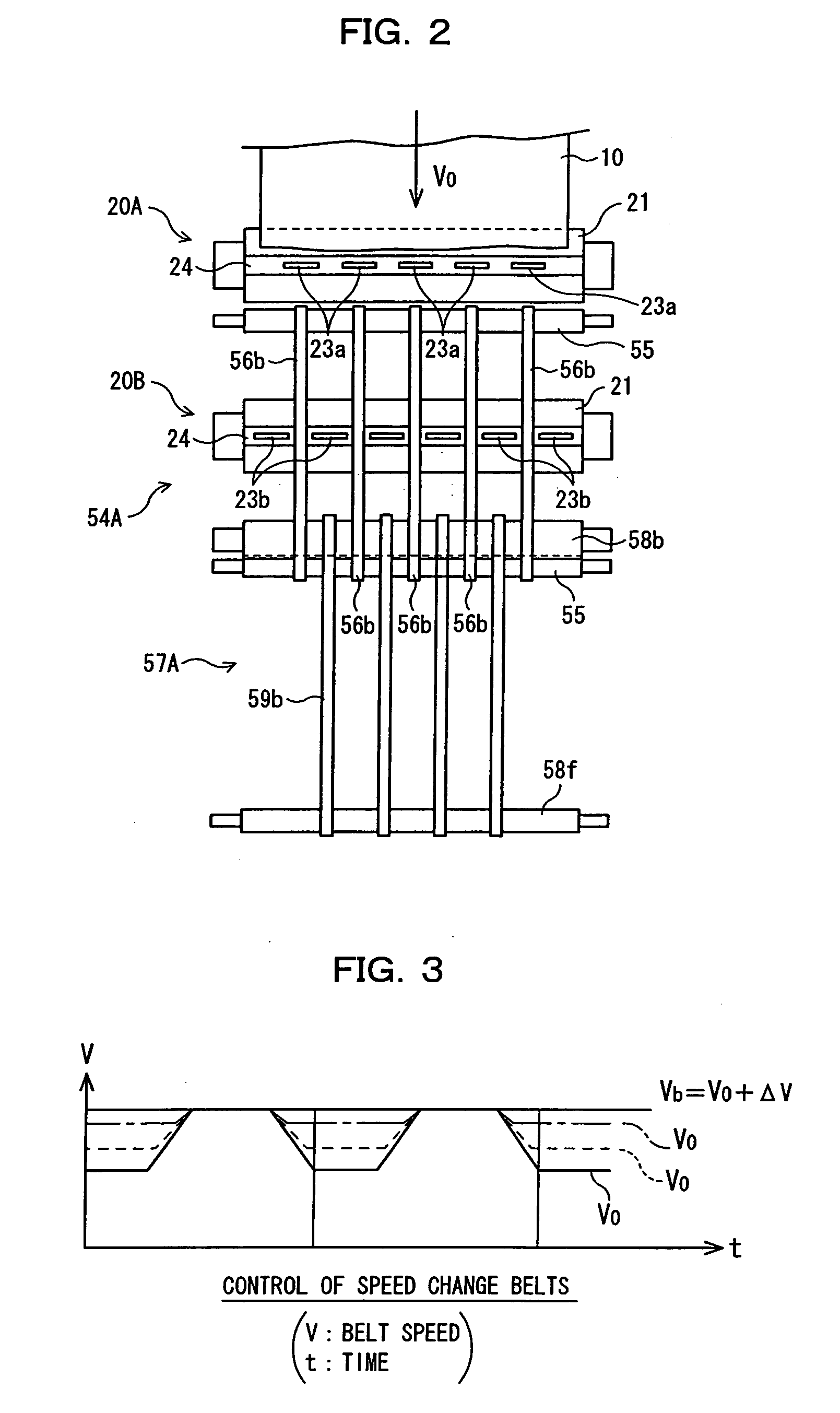
[0134] Initially, a first embodiment of the disclosed embodiment will be described. FIGS. 1 to 3 show a folding machine for a rotary printing machine constructed in accordance with the first embodiment of the disclosed embodiment. FIG. 1 is a schematic side view showing the construction of the folding machine; FIG. 2 is a schematic front view (taken in a direction indicated by an arrow A in FIG. 1) showing the essential parts; and FIG. 3 is a speed characteristic diagram used to explain how control of speed change belts is performed. Note in FIGS. 1 and 2 that the same parts as those of the conventional example (FIGS. 22 to 24) are given the same reference numerals.

[0135] For example, as shown in FIG. 22, a rotary printing machine according to this embodiment comprises eight major parts: a paper feeder part 1; an infeed part 2; a printing part 3; a drying part 4; a cooling part 5; a web passing part 6; a folding machine 7; and a paper discharger part 8 for discharging a sheet folde...

second embodiment

[0166] Next, a second embodiment of the disclosed embodiment will be described. FIGS. 4 to 9 show a folding machine for a rotary printing machine constructed in accordance with the second embodiment of the disclosed embodiment. FIG. 4 is a schematic side view showing the essential parts of the folding machine and FIGS. 5 to 9 are schematic side views used to explain how a sheet 10a is delivered. Note in FIGS. 4 to 9 that the same parts as those of FIGS. 1 and 2 are given the same reference numerals and therefore a description of the same parts is partially omitted. In FIGS. 4 to 9, it is shown that a web 10 and a sheet 10a are horizontally conveyed. However, as with the first embodiment, they are conveyed in a vertical direction.

[0167] The folding machine 7 of this embodiment is disposed downstream of the drag roller 11 and triangular plate 12 (see FIG. 23). As shown in FIG. 4, as with the first embodiment, from the upstream side the folding machine 7 is equipped with an upstream b...

third embodiment

[0195] Next, a third embodiment of the disclosed embodiment will be described. FIGS. 10(a) to 13(d) show a folding machine for a rotary printing machine constructed in accordance with the third embodiment of the disclosed embodiment. FIGS. 10(a) and 10(b) are schematic diagrams used to explain the principle of a non-circular drive roller; FIG. 11 is a schematic diagram used to explain the drive speed of the non-circular drive roller; FIGS. 12(a) to 12(c) are schematic diagrams used to explain operation of the non-circular drive roller; and FIGS. 13(a) to 13(d) are schematic diagrams used to explain variations of the non-circular drive roller.

[0196] In this embodiment, attention is paid to the drive system for the speed change conveyor belts 59c, 59d used in the downstream belt conveyor of the first and second embodiments, and the periodic speed modulation of a speed change conveyor belt is performed without controlling the speed of a drive source such as a motor, etc. More specific...


PUM

PropertyMeasurementUnit
cut-off lengthaaaaaaaaaa
conveying speedaaaaaaaaaa
speedaaaaaaaaaa

Abstract

In a variable cut-off length type rotary printing machine, to perform processes such as a process of folding a cut-off sheet with a high degree of accuracy, a folding machine includes a cut-off unit capable of varying and cutting a cut-off length of a web fed from a printing machine of the rotary printing machine, and a processor (such as a folder, etc.) for processing a sheet 10a cut off by the cut-off unit. Between the cut-off unit 50 and the processor, the folding machine further includes a first belt conveyor for conveying the sheet at a speed equal to the web, and a second belt conveyor for receiving the sheet from the first belt conveyor at a speed approximately equal to the sheet conveying speed of the first belt conveyor, then varying the conveying speed to a speed approximately equal to the sheet conveying speed of the processor, and delivering the sheet to processor.

Description

RELATED APPLICATIONS [0001] The present application is based on International Application PCT / JP2004 / 18294, and claims priority from, Japanese Application Number 2003-415124, filed Nov. 18, 2003, the disclosure of which is hereby incorporated by reference herein in its entirety.TECHNICAL FIELD [0002] The disclosed embodiments relates to a folding machine installed in a rotary printing machine, and more particularly to a folding machine that is employed in a variable cut-off length type rotary printing machine in which the cut-off length of a web can be varied. BACKGROUND ART [0003]FIG. 22 is a schematic diagram showing an example of a commercial offset type rotary printing machine that is one of the rotary printing machines, FIG. 23 is a schematic diagram showing an example of a folding machine (comprising a web cutting unit and a paper discharger) adopted in the commercial offset type rotary printing machine, and FIG. 24 is a schematic diagram for explaining an example of the catch...

Claims


Application Information

Patent Timeline
Patent Type & Authority Applications(United States)
IPC IPC(8): B41F13/58B41F13/56B31B50/16B65H45/28
CPCB65H2513/108B65H45/28B65H2513/10
Inventor SHOJI, YUKIKAZUMOTOOKA, MIKIOMITAMURA, ISAMISHICHIJO, KUNIHIRO
Owner MITSUBISHI HEAVY IND PRINTING & PACKAGING MACHINERY
Why Eureka
Try Eureka