Fuse

a technology of fuse and alloy, applied in the field of fuse, can solve the problems of affecting the performance of fusible alloy pieces, affecting the safety of users, and changing the amount of current that melts and breaks the fusible alloy pieces, etc., and achieves the effect of reducing the differences in product performance and being manufactured more easily

Inactive Publication Date: 2019-07-02
TOYODA IRON WORKS CO LTD
View PDF19 Cites 0 Cited by
  • Summary
  • Abstract
  • Description
  • Claims
  • Application Information

AI Technical Summary

Benefits of technology

[0019]The fuse of the present invention has the advantage that the fuse reduces differences in performance between products and can be manufactured more easily.

Problems solved by technology

Thus, the quality of welding may change the amount of current that melts and breaks the fusible alloy piece.

Method used


Image

  • Fuse
  • Fuse
  • Fuse

Examples


first embodiment

[0036]A first embodiment of a fuse will now be described. The fuse is arranged, for example, between a battery and an inverter of a hybrid vehicle.

[0037]Structure

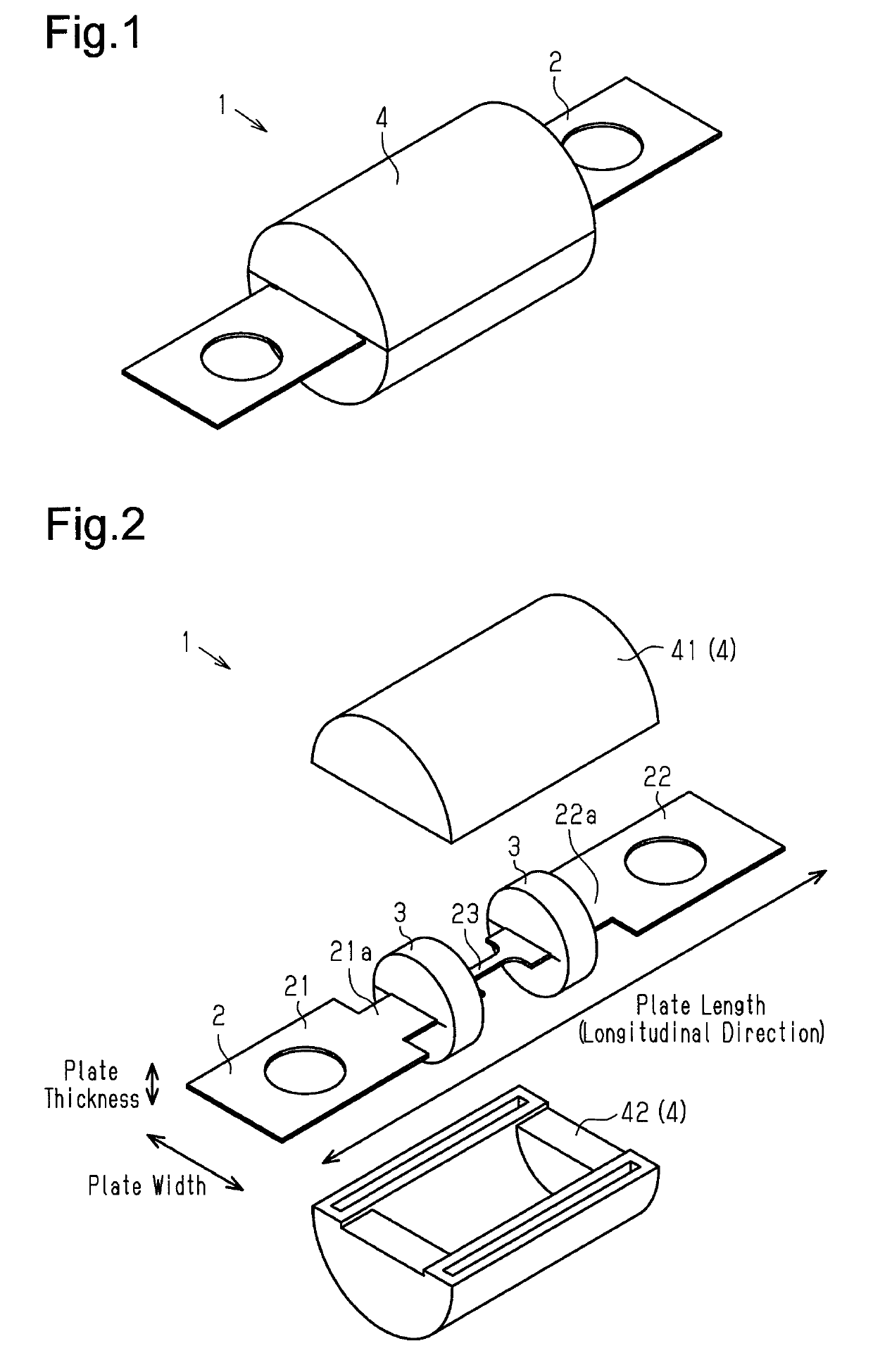
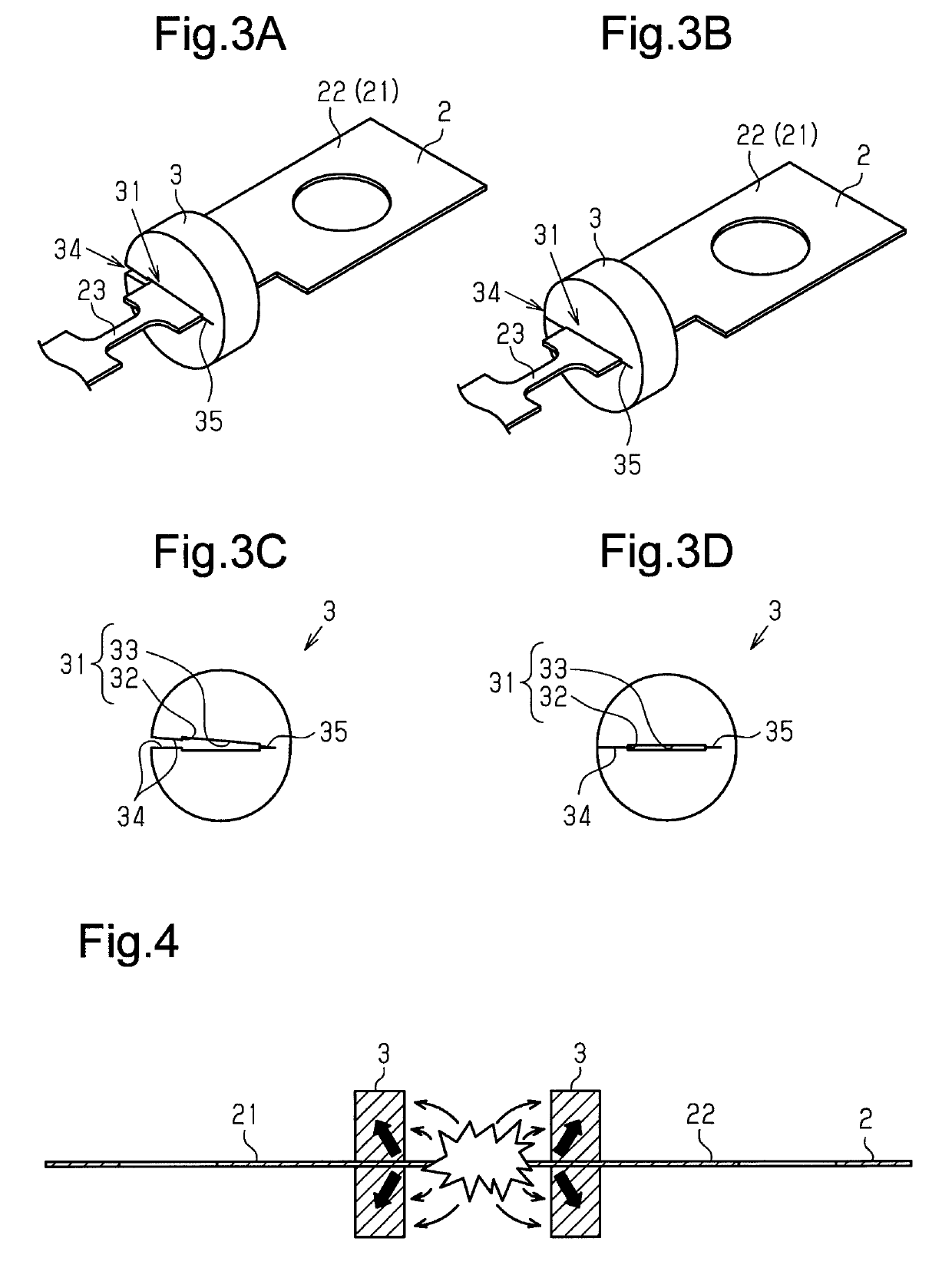
[0038]As shown in FIGS. 1 and 2, the fuse 1 includes a bus bar 2, two blocks 3, and a case 4.

[0039]As shown in FIG. 2, the bus bar 2 is elongated as a whole and formed from a conductive metal such as copper. The bus bar 2 includes a first bar 21 and a second bar 22 that extend in a longitudinal direction and an element 23 that connects the first bar 21 and the second bar 22 in the longitudinal direction. The first and second bars 21 and 22 are formed integrally with the element 23. The first and second bars 21 and 22 are equal in plate width, plate thickness, and length (plate length) in the longitudinal direction. The width of the element 23 is less than the plate widths of the first and second bars 21 and 22, more specifically, the plate widths of block coupling portions 21a and 22a that are portions of the first and seco...

second embodiment

[0066]A second embodiment of the fuse will now be described. The fuse of the second embodiment mainly differs from the fuse of the first embodiment in that the blocks are integrated with the case. Thus, like or same reference numerals are given to those components that are the same as the corresponding components of the first embodiment. Such components will not be described in detail.

[0067]Structure

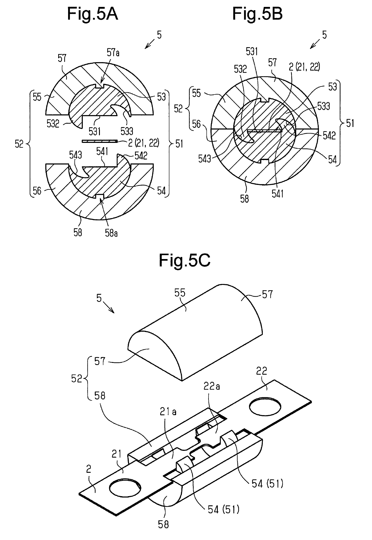
[0068]As shown in FIG. 5C, the fuse 5 includes the bus bar 2, two blocks 51, and a case 52.

[0069]As shown in FIGS. 5A and 5B, each block 51 includes a first block member 53 and a second block member 54. The first and second block members 53 and 54 each have a semi-cylindrical shape obtained by cutting a cylinder having a diameter (outer diameter) that is greater in dimension than the plate widths of the first and second bars 21 and 22 (block coupling portions 21a and 22a) along the diameter. The block 51 is cylindrical as a whole when the first and second block members 53 and 54 are coup...


PUM


Abstract

Provided herein is a fuse that includes a conductive member, two shielding portions arranged on the conductive member, and a case. The conductive member includes a two bars on each end of the conductive member and an element (e.g., melting portion) that integrally connects the two bars. The two shielding members are disk shaped and are situated on the conductive member between the element and the two bars. The case encloses the element and the two shielding members.

Description

RELATED APPLICATIONS[0001]The present invention is a U.S. National Stage under 35 USC 371 patent application, claiming priority to Serial No. PCT / JP2016 / 066323, filed on 2 Jun. 2016; which claims priority of JP 2015-116003, filed on 8 Jun. 2015, the entirety of both of which are incorporated herein by reference.TECHNICAL FIELD[0002]The present invention relates to a fuse.BACKGROUND ART[0003]A known fuse is arranged between a power supply and an electric circuit to limit situations in which overcurrent adversely affects the function of the electric circuit or an electric device.[0004]Patent document 1 describes a fuse that includes two conductors each including a flanged bulging head, a fusible alloy piece located between and connected through welding to the two bulging heads that oppose each other in a direction in which the conductors extend, and a tubular insulator that accommodates the two bulging heads and the fusible alloy piece.[0005]In this fuse, the fusible alloy piece has a...

Claims


Application Information

Patent Timeline
Patent Type & Authority Patents(United States)
IPC IPC(8): H01H85/20H01H85/175H01H85/055H01H85/18H01H85/10
CPCH01H85/20H01H85/055H01H85/185H01H85/175H01H85/18H01H85/10
Inventor KAWAI, SHUNSUKESAKAI, HIDEAKISONE, YASUHIROIWATA, KUNIHIRO
Owner TOYODA IRON WORKS CO LTD
Why Eureka
Try Eureka