Zone control system for conveyor system

a conveyor system and control system technology, applied in the field of conveyor systems, can solve the problems of limiting the amount of data that can be communicated, increasing the number of data messages that pass through the control system, and requiring individual wiring between the controllers that is expensive and time-consuming to assemble, so as to achieve simple and effective, simplify the configuration, and simplify the effect of

Active Publication Date: 2019-07-02
NOVA TRON CONTROLS CORP
View PDF15 Cites 5 Cited by
  • Summary
  • Abstract
  • Description
  • Claims
  • Application Information

AI Technical Summary

Benefits of technology

[0024]In one embodiment, local communications are used to implement the self-repair and automatic configuration functionalities. In this embodiment, each zone controller may include an upstream communications port for directly communicating with the upstream zone controller on a one-to-one basis and a downstream communications port for directly communicating with the downstream zone controller on a one-to-one basis. The use of direct local communications ensures that each zone controller is communicating with the correct upstream and downstream zone controllers without the need to know the identification of those zone controllers, thereby avoiding the need to pre-configure or pre-program a zone controller to enable local communications.
[0025]The present invention provides a simple and effective zone controller system for a conveyor system. The use of global communications between zone controllers allows each zone controller to make intelligent decisions informed by information available from all other zone controllers on the global network. The use of direct one-to-one communications allows a zone controller to implement self-repair functionality without the need for any related pre-configuration. Similarly, the use of direct one-to-one communications allows a new replacement zone controller to be automatically recognized and configured by other zone controllers without the need for any related pre-configuration. The use of programmable logic equations to define operation of each zone controller not only simplifies configuration, but also provide a simple and effective way of making zone controller actions dependent on a wide range of variables that might be obtain from other zone controllers on the global network. Further, the self-repair functionality dramatically simplifies the process of repairing and / or replacing zone controllers. The use of automatic self-diagnostic can allow repair and / or replacement to occur without any user intervention. By storing the configuration parameters on a plurality of different zone controllers, the system provides a layer of redundancy that may help to ensure proper repair and / or replacement of a zone controller.

Problems solved by technology

ZPA avoids having a stack up of payloads queuing at the end of a conveyor where the pressure builds on the end payload, possibly causing damage.
This greatly restricts the data that can be communicated.
It also requires individual wiring between controllers that is expensive and time consuming to assemble.
But as the number of conveyor zones increase, the number of data messages to pass through a zone controller increases dramatically, and consumes zone controller resources.
The data messages are kept very short and the amount of data limited.
Real-time data messaging cannot be achieved.
This often becomes a logistics problem when it is necessary to interface to multiple devices along the conveyor.
But, issues may arise when a zone controller fails and must be replaced.
When the options are in memory and the zone controller fails, it becomes harder.
In may have been months or years since the zone controller was first configured and trying to find what the options were can be problematic.
It can be difficult to determine if the options were documented for each zone controller in the system.
Even if the options where properly documented, the documentation may be difficult to locate—particularly after a long period of time.
Experience has revealed that this problem is very common.
But these methods are time consuming and problematic, and keep the conveyor offline for an extended period.
Further, no known ZPA controller systems have the ability to connect with an external network for monitoring or updating.

Method used


Image

  • Zone control system for conveyor system
  • Zone control system for conveyor system
  • Zone control system for conveyor system

Examples


Embodiment Construction
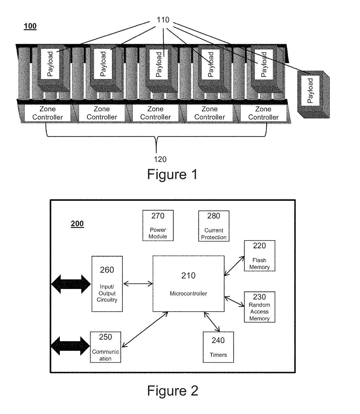
[0043]Overview

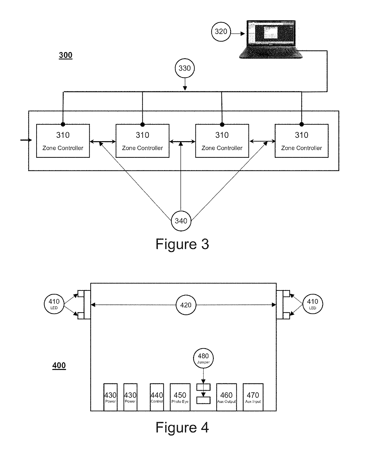
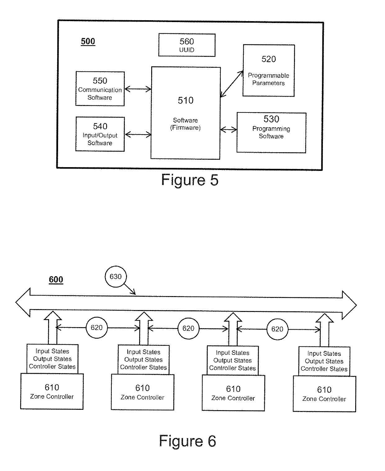
[0044]A conveyor system 100 having a zone controller system 10 in accordance with an embodiment of the present invention is shown in FIG. 1. The zone controller system 10 includes a plurality of zone controllers 120 that are interconnect by a global communication network 330 and a local communication network 340. The global communication network 330 allows each zone controller 120 to share data with every other zone controller 120, while the local communication network 340 allows each zone controller 120 to share select data with adjacent zone controllers 120. Each zone controller may globally communicate the state of its inputs, the state of its outputs and its controller state. Each zone controller may locally communicate the status of the payload in the zone to the adjacent controllers. In this embodiment, essentially any information obtained through global communications or local communication can be utilized in dictating operation of a zone controller. The zone co...


PUM


Abstract

A zone controller system that includes global communication of inputs, outputs and controller states from all zone controllers allowing each zone controller to operate based on inputs, outputs and controller states from all other zones. The zone controller system may also include direct one-to-one communication connections that allow additional communications. The system may include a user interface to configure operation of the zone controllers utilizing programmable logic equations that may use as variables the inputs, outputs and controller states of any zone controller. The user interface may be implemented in an off board configuration tool that is run on a computer connected to the global network. The system may also utilize one-to-one communications connections to provide self-repair and auto-configuration features. Each zone controller may store its ID(s) and configuration parameters on two other zone controllers, where they can be recovered for self-repair and auto-configuration.

Description

BACKGROUND OF THE INVENTION[0001]The present invention relates to conveyor systems and more particularly to zone control systems for conveyor systems.[0002]Conveyor systems move desired payloads from one place to another in an orderly fashion. Rollers or belts are used to move the payloads. An example of a payload may be a cardboard box, a shipping container, a wooden pallet, or an automotive steel component. Within a conveyor system, there are often points, often called stations, along its length with varied equipment used to do work on the payload as it moves to its end destination. At each station an action or function is performed on the payload. Depending on the function to be performed, the conveyor may stop, a payload may be removed, or the conveyor may continue to move the payload. In addition to these stations, there are often merges, diverges, and intersections with other conveyors systems that moves the payload to and from those conveyor systems. A large number of inputs ...

Claims


Application Information

Patent Timeline
Patent Type & Authority Patents(United States)
IPC IPC(8): H04L12/40
CPCH04L12/40H04L2012/40215
Inventor KACEL, RICHARD J.
Owner NOVA TRON CONTROLS CORP
Why Eureka
Try Eureka