Light source with adapted spectal output

a technology of spectral output and light source, which is applied in the direction of fluorescence/phosphorescence, lighting support devices, treatment rooms, etc., can solve the problems of difficult detection of fluorescent signals, and achieve the effect of enhancing fluorescent signals

Inactive Publication Date: 2019-07-09
SIGNIFY HLDG BV
View PDF36 Cites 2 Cited by
  • Summary
  • Abstract
  • Description
  • Claims
  • Application Information

AI Technical Summary

Benefits of technology

[0018]Since the spotlight produces generally white light, preferably having a color point on or near the black body line as represented in the CIE chromaticity diagram, it provides general illumination of high quality for many application, including surgery.
[0026]In yet another aspect, the invention provides the use of a spotlight as described herein for illuminating an object comprising a fluorescent molecule. In some embodiments, the fluorescent molecule emits light in a wavelength range corresponding to a wavelength range in which the spotlight produces no or low intensity light emission. In some embodiments, the spotlight produces an emission spectrum comprising an emission peak in a wavelength range where the fluorescent molecule has an absorption peak; hence the emission from the spotlight may provide primary light for conversion by the fluorescent molecule and thus enhance the fluorescent signal.
[0030]controlling the operation at least one solid state light emitting element or a shielding member, respectively, to prevent or reduce emission of light of a wavelength range emitted by the object to be illuminated; and

Problems solved by technology

However, the fluorescent signal can be difficult to detect, especially in a surgical environment which requires strong lighting.

Method used


Image

  • Light source with adapted spectal output
  • Light source with adapted spectal output
  • Light source with adapted spectal output

Examples


Embodiment Construction

[0051]The present invention will now be described more fully hereinafter with reference to the accompanying drawings, in which currently preferred embodiments of the invention are shown. This invention may, however, be embodied in many different forms and should not be construed as limited to the embodiments set forth herein; rather, these embodiments are provided for thoroughness and completeness, and fully convey the scope of the invention to the skilled person.

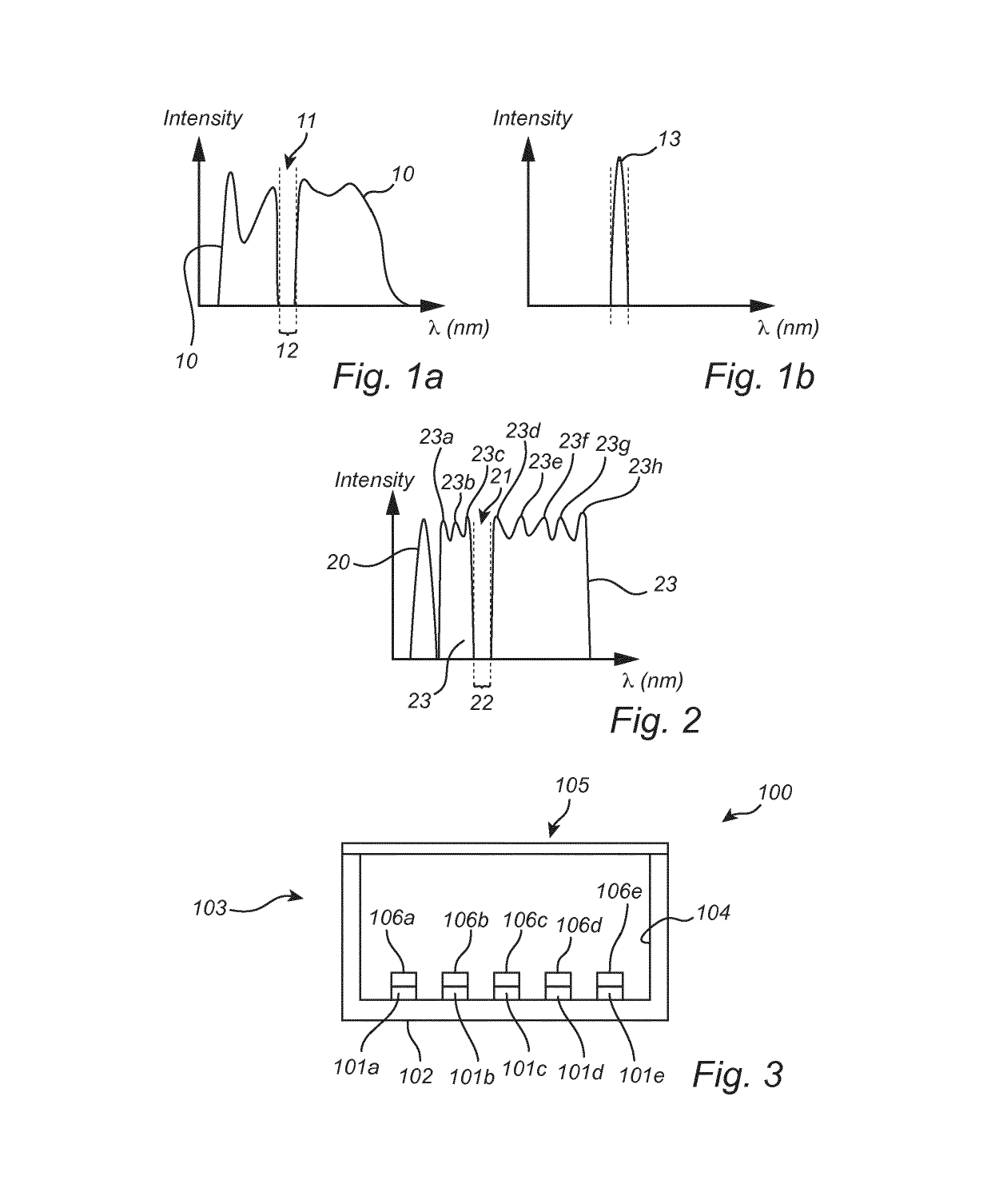
[0052]The present inventors have realized that during the examination of a tissue injected with a fluorescent biomarker during surgery, the surgical light can overlap with the emission from the marker, which makes the fluorescence from the biomarker difficult to discern. The inventors have found that the use of a light source, typically a spotlight, having a “hole” or “dip” in the emission intensity spectrum at a wavelength band which corresponds to the emission of the fluorescent marker molecule can increase the detectabil...


PUM

PropertyMeasurementUnit
FWHMaaaaaaaaaa
wavelength rangesaaaaaaaaaa

Abstract

The white light spotlight for luminescence (e.g. biomarker) detection according to the present application includes: at least one solid state light emitting element to emit primary light, and a plurality of wavelength converting materials, to convert part of primary light into secondary light, provided as an array of independent wavelength converting domains, wherein different domains comprise converting materials producing different secondary light emission bands / peaks, each converting material being adapted to convert primary light into secondary light, wherein each converting material is adapted to contribute to the total emission spectrum with at least one emission band / peak and the total secondary light emission provided by said converting materials provides a broad band emission spectrum except for at least one defined narrow wavelength range in which the spotlight produces no or significantly reduced light emission, and wherein the combined light emission from the converting materials is controllable to form said spectrum.

Description

CROSS-REFERENCE TO PRIOR APPLICATIONS[0001]This application is the U.S. National Phase application under 35 U.S.C. § 371 of International Application No. PCT / EP2014 / 058810, filed on Apr. 30, 2014, which claims the benefit of European Patent Application No. 13166395.7, filed on May. 3, 2013. These applications are hereby incorporated by reference herein.FIELD OF THE INVENTION[0002]The present invention relates to solid state light-emitting arrangements, devices and lighting systems utilizing wavelength converting materials for providing a desirable spectral output.BACKGROUND OF THE INVENTION[0003]Fluorescent biomarkers (biological markers) are fluorescent molecules that can be used for detecting a biological state or process, such as a pathogenic state or process or a particular cell or tissue type. Fluorescent biomarkers can for example be used for detecting diseases such as cancer. The fluorescent molecules can be injected into a patient or a biological sample and accumulate at the...

Claims


Application Information

Patent Timeline
Patent Type & Authority Patents(United States)
IPC IPC(8): A61B5/00G01N21/64F21V21/084H01L25/075F21L4/00F21K9/64F21V9/30H05B33/08F21L4/02H01L33/50F21W131/205F21Y115/10H05B44/00
CPCG01N21/6447A61B5/0071F21K9/64F21L4/005F21V9/30F21V21/084G01N21/6428G01N21/6486H01L25/0753H05B33/0872H01L2924/0002F21L4/027F21W2131/205F21Y2115/10G01N2021/6439G01N2021/6471G01N2201/062G01N2201/068H01L33/504H01L33/508H01L2924/00H05B45/20F21V9/40F21V13/08F21V9/38A61B5/00
Inventor VAN BOMMEL, TIESHIKMET, RIFAT ATA MUSTAFA
Owner SIGNIFY HLDG BV
Why Eureka
Try Eureka