Foldable, deployable and reconfigurable origami antennas using fabric, textile or other material encapsulation and/or scaffolding

a technology of origami antennas and fabric, applied in the direction of antenna details, electrically long antennas, antennas, etc., can solve problems such as difficult movement, and achieve the effect of reducing the volume of foldable antennas

Active Publication Date: 2019-07-09
FLORIDA INTERNATIONAL UNIVERSITY
View PDF8 Cites 8 Cited by
  • Summary
  • Abstract
  • Description
  • Claims
  • Application Information

AI Technical Summary

Benefits of technology

The invention is about a new type of foldable antenna that has two layers and a bunch of small folded pieces placed inside. This design makes the antenna easier to fold up and takes up less space when expanded.

Problems solved by technology

Even though these HAs and SHAs have many merits, they need a large height, so it is not easy to move them.

Method used


Image

  • Foldable, deployable and reconfigurable origami antennas using fabric, textile or other material encapsulation and/or scaffolding
  • Foldable, deployable and reconfigurable origami antennas using fabric, textile or other material encapsulation and/or scaffolding
  • Foldable, deployable and reconfigurable origami antennas using fabric, textile or other material encapsulation and/or scaffolding

Examples


example 1

[0053]FIG. 8(a) shows a measured return loss of a foldable antenna according to an embodiment of the subject invention. FIG. 8(b) shows a measured axial ratio of the foldable antenna, and FIG. 8(c) shows a measured left-hand circular polarization (LHCP) gain of the foldable antenna. Referring to FIGS. 8(a)-8(c), the foldable antenna has excellent performance as an antenna in both the unfolded state and the folded state while having a foldable characteristic to reduce the volume.

example 2

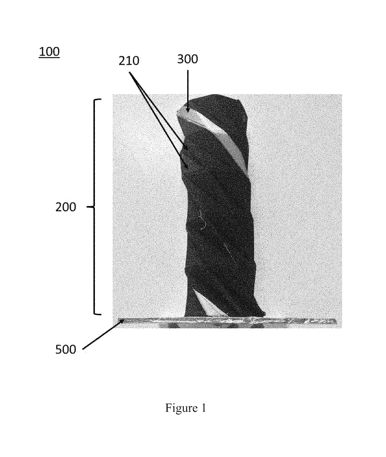
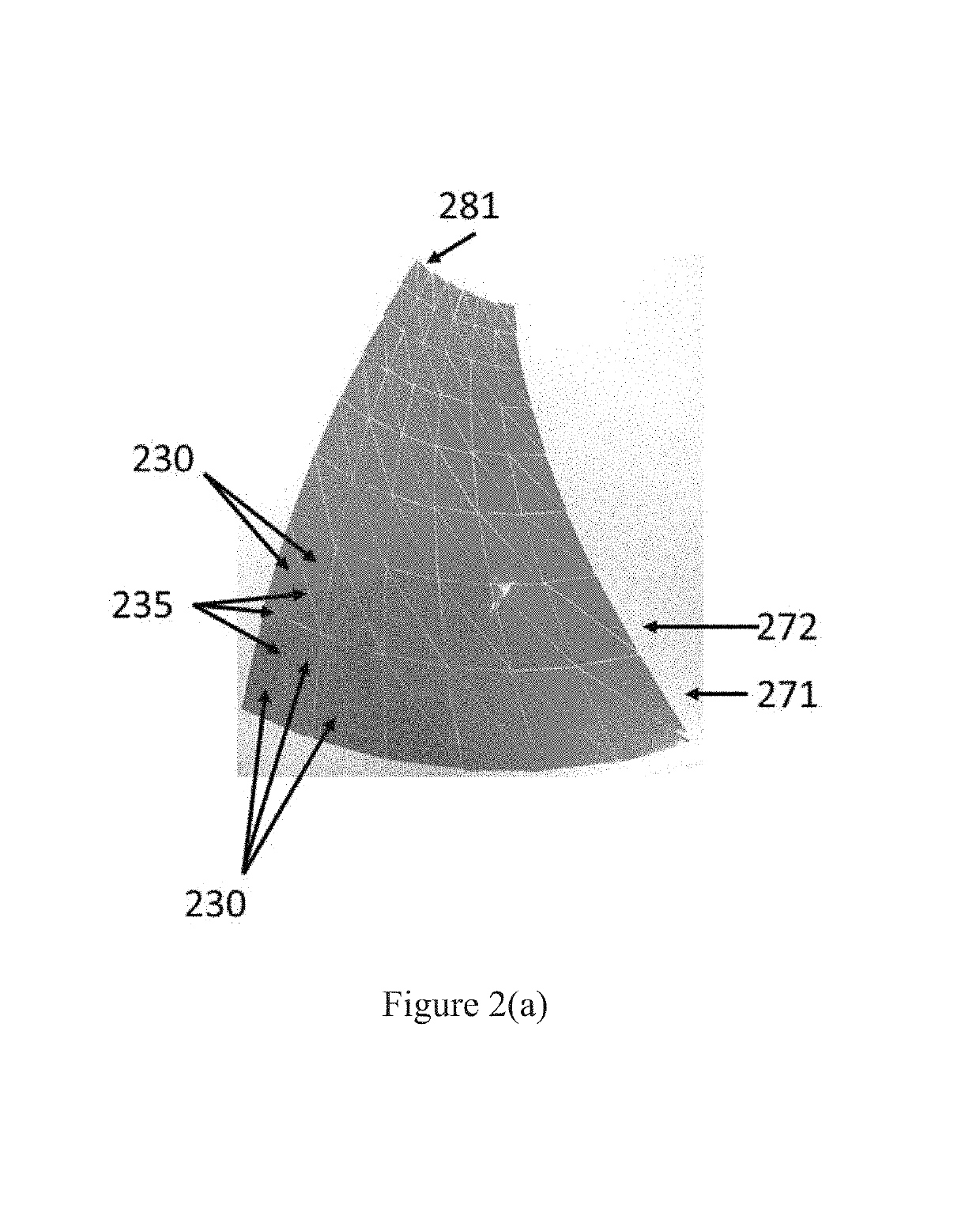
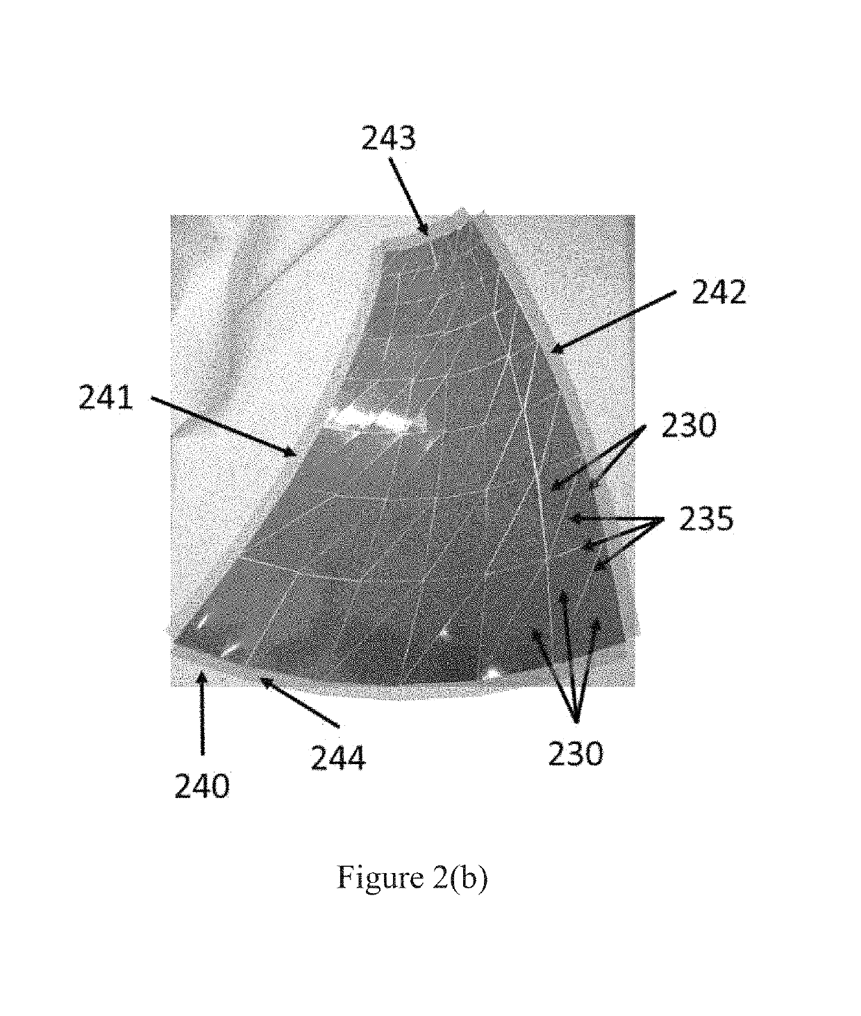
[0054]FIGS. 9(a) and 9(b) show an unfolded state and a folded state of a foldable antenna according to an embodiment of the subject invention. Referring to FIGS. 9(a) and 9(b), the bottom and top encapsulation layers are made of fabric and a thick origami plastic substrate is sandwiched between two fabric layers. The thickness of the foldable antenna was 29 mil (thousandths of an inch), including a first thickness of 7 mil of the thick origami plastic substrate, a second thickness of 20 mil of the two fabric layers, and a third thickness of 2 mil of the glue. The final origami cone was formed by stitching the origami 2D structure into a 3D structure, thereby resulting in the popping fabric origami cone shown in FIGS. 9(a) and 9(b).

example 3

ons

[0055]FIGS. 10(a)-10(c) show a plurality of applications of foldable antennas according to embodiments of the subject invention. For example, a foldable antenna can be applied to a moving vehicle, an individual apparatus, or a satellite. In the moving vehicle, the foldable antenna can provide multi-functional communications and can be deployable or collapsible. In the individual apparatus, the foldable antenna can be used as a tactical antenna. In the satellite, the foldable antenna can be used as a spaceborne and airborne antenna.


PUM


Abstract

A foldable antenna can comprise a bottom encapsulation layer, a plurality of origami substrates disposed on the bottom encapsulation layer, a top encapsulation layer disposed on the plurality of origami substrate, and a conductive trace disposed on the top encapsulation layer. The plurality of origami substrates can be spaced apart from each other. The bottom encapsulation layer and the top encapsulation layer can comprise a fabric, and each of the plurality of origami substrates can comprise at least one of foam, plastic, carton, FR4, laminate, and wood.

Description

STATEMENT OF GOVERNMENT SUPPORT[0001]This invention was made with government support under Grant No. EFRI 1332348 awarded by the National Science Foundation. The government has certain rights in the invention.BACKGROUND[0002]Axial mode conventional helical antennas (HAs) have been widely used in satellite communications and global positioning systems due to their high gain and circular polarization. The properties of conventional helical antennas have been extensively studied. Segmented helical antennas (SHAs), such as square cross section helical antennas, have been investigated. SHAs can provide approximately equivalent performance compared to the conventional helical antenna. The linear segments, which make up an SHA, can be easily supported on a dielectric structure. This kind of structure can be designed and manufactured at a very low cost. Even though these HAs and SHAs have many merits, they need a large height, so it is not easy to move them.BRIEF SUMMARY[0003]Embodiments of...

Claims


Application Information

Patent Timeline
IPC IPC(8): H01Q1/36H01Q1/08H01Q1/38
CPCH01Q1/085H01Q1/38H01Q1/362H01Q1/08H01Q1/273H01Q1/288H01Q1/3275H01Q11/086H01Q15/161
Inventor GEORGAKOPOULOS, STAVROS
Owner FLORIDA INTERNATIONAL UNIVERSITY
Why Eureka
Try Eureka