

Electronic tuning system
a technology of electronic tuning and tuning system, applied in the field of electronic tuning system, can solve the problems of unsuitability of continuously variable reactance techniques common in radio design, system very sensitive to tuning errors, and severe restriction of bandwidth for any communication channel associated with the bandwidth
- Summary
- Abstract
- Description
- Claims
- Application Information
AI Technical Summary
Benefits of technology
Problems solved by technology
Method used
Image

Examples
Embodiment Construction
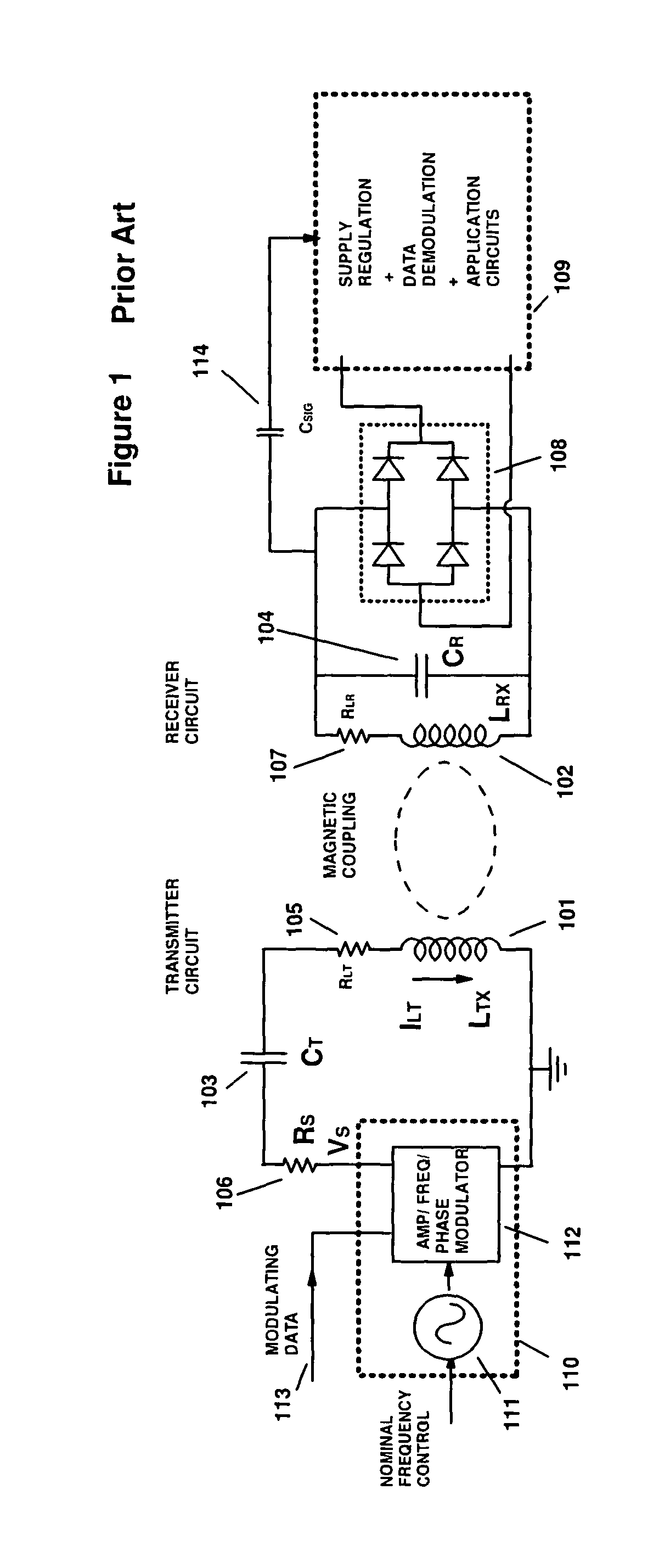
[0001]In inductively coupled systems such as radio frequency identification (RFID), implanted biomedical devices or wireless charging it is desirable to have a transmitter or reader function that generates a strong magnetic field with a minimum power for the transmitter circuitry. As a result, it is desirable to use an antenna inductor in a resonant circuit with a high quality factor (Q), since a high Q gives a high circulating current with a lower drive voltage. However, makes the system very sensitive to tuning errors due to component manufacturing tolerances and post manufacture parametric drift from environmental factors and ageing. A further problem arising from a high Q antenna coil is the severe restriction it places on the bandwidth for any communication channel associated therewith, whether the modulation employed is amplitude, frequency or phase or some combination thereof. These problems apply similarly to other electronic systems and diverse applications employing induct...
PUM
 Abstract
Description
Claims
Application Information