Distillation reflux reduction

a technology of distillation and reflux reduction, which is applied in the direction of azeotropic distillation, separation process, transportation and packaging, etc., can solve the problems of reducing the product output (“capacity”) of the rectifier column, limiting the amount of product produced in a column of a given diameter, and limiting the quantity of reflux needed in fractional distillation. achieve the effect of reducing the amount of reflux and reducing the energy consumed

Active Publication Date: 2019-07-16
BIOLEAP INC
View PDF12 Cites 0 Cited by
  • Summary
  • Abstract
  • Description
  • Claims
  • Application Information

AI Technical Summary

Benefits of technology

[0012]Embodiments of the present invention may combine an enriched fluid (e.g. a mixture having a higher content of the desired constituent than does the reflux liquid) with the reflux liquid at a location upstream of the rectifier column but downstream of any liquid / vapor equilibrium interface, and downstream of any diversion of fluid away from the rectifier column. This results in a most efficient use of the enriched fluid, whether it is costly high proof vapor sourced from a dehydrator, or it is a fluid taken from elsewhere in the reflux fluid loop. The present invention allows for a reduction in the amount of reflux used to obtain a target separation when compared to the prior art method of FIG. 1, thereby reducing the energy consumed in the process.
[0014]The advantage of this arrangement is substantial. Mechanically altering the composition of the reflux stream of a minimum-boiling azeotropic mixture, bringing it more near its natural azeotrope, necessary reduces the reflux ratio required in order to produce the same overhead vapor composition as without the mechanical action. The economic benefit of this arrangement is great when applied to real world applications. The mechanical energy is typically derived from an existing reflux pump 26, which typically discharges the subcooled distillate at a pressure greater than the minimum theoretical requirement. In practice, the excess pressure is reduced by use of a back pressure control device, such as a control valve (not shown in FIG. 1). Since most of the capital equipment is already installed and much of the necessary mechanical energy is already being generated and wasted, relatively little additional capital or energy is required to install and operate a system consistent with the present invention.

Problems solved by technology

However, the recycled reflux flow reduces the product output (“capacity”) of the rectifier column.
This procedure significantly limits the amount of product produced in a column of a given diameter, since most of the condensed vapors have to be recycled back to the rectifier column as reflux liquid.
To date, there has been limited success in reducing the quantity of reflux necessary in the fractional distillation of a minimum-boiling azeotropic mixture.
Entrainers have been used successfully across a wide variety of industries, but they add cost, may be difficult or dangerous to handle, and ultimately must be removed from the final product stream.

Method used


Image

  • Distillation reflux reduction
  • Distillation reflux reduction
  • Distillation reflux reduction

Examples


Embodiment Construction

[0020]The present inventors have innovatively recognized several disadvantages with the prior art reflux configuration of FIG. 1.

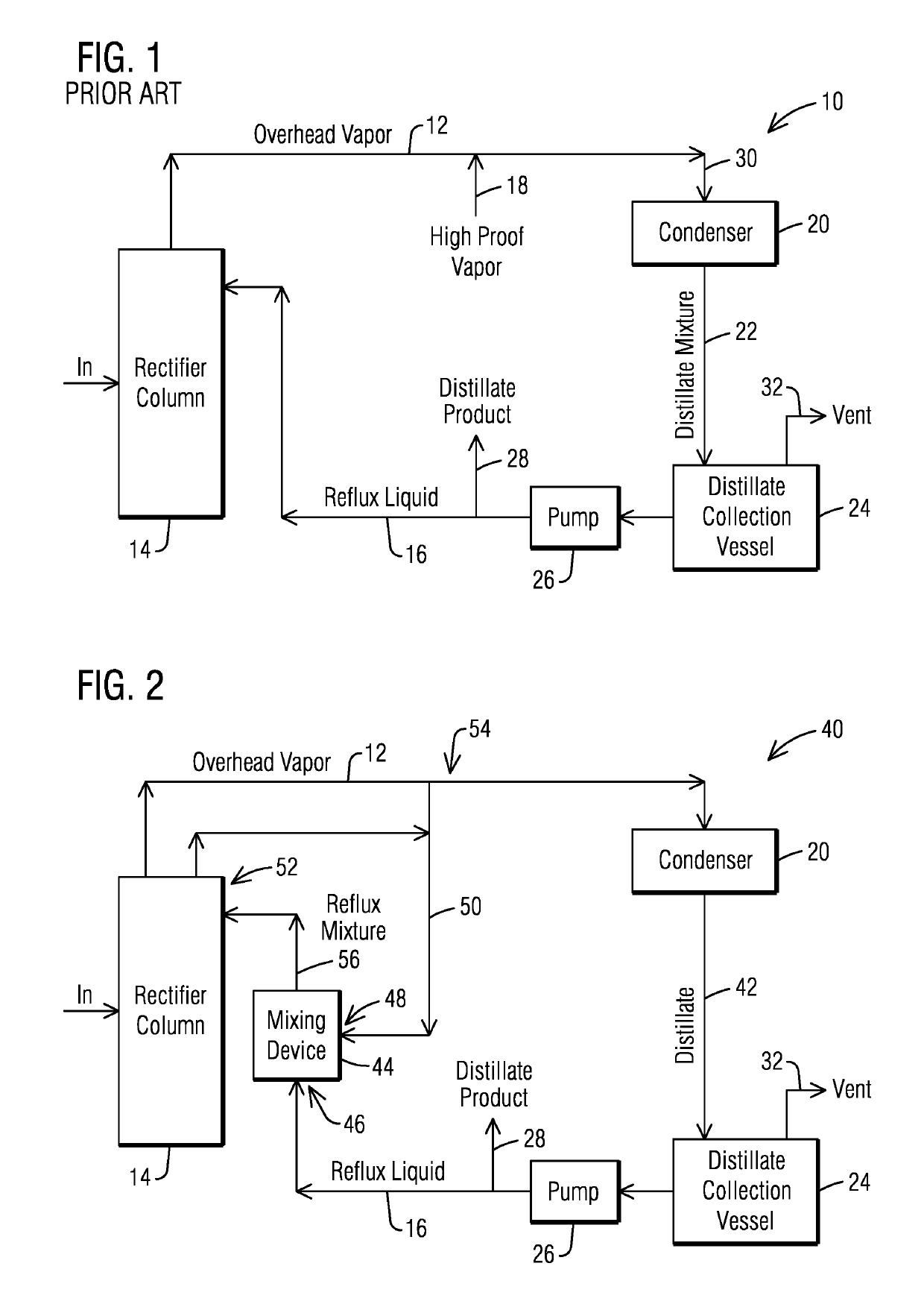
[0021]First, while the mixing of the high proof vapor 18 with the overhead vapor 12 does provide a higher proof vapor mix 30 to the condenser 20, the resulting distillate mixture 22 will, by definition, be a lower proof composition than the vapor mix 30 due to the liquid / vapor interface existing within the condenser 20.

[0022]Second, the volume of vapor exiting the distillation system through the vent 32 is not affected by the addition of the high proof vapor 18, and the vapor vented will be superior in concentration than the vented vapor would be without the addition of the high proof vapor 18. Therefore, the vent 32 will discharge a relatively larger quantity of ethanol and a relatively lower quantity of water than would be vented if no high proof vapor 18 were introduced, and the addition of the high proof vapor 18 results in an increase in ethanol lost ...


PUM


Abstract

An improvement which reduces the reflux requirement for a fractional distillation system of an alcohol production plant (40, 60, 70, 80). The improvement includes a mixing device (44) for combining a water / alcohol mixture having an enhanced alcohol content (50, 62, 72, 82) with the reflux liquid (16) in the absence of a vapor / liquid equilibrium interface to form a reflux mixture (56) for supply to the rectifier column (14). The mixture having an enhanced alcohol content may be sourced from a location along the rectifier-reflux vapor to liquid system flow path, or from another source.

Description

[0001]This application claims benefit of the 15 Jul. 2016 filing date of U.S. provisional application No. 62 / 362,828.FIELD OF THE INVENTION[0002]This invention relates generally to distillation processes, and more particularly to the reduction of the amount of reflux used in a fractional distillation process, and in one embodiment to the reduction of the amount of reflux liquid used in a grain alcohol plant.BACKGROUND OF THE INVENTION[0003]In a typical fuel grade ethanol production process such as may be used in a corn ethanol plant, beer having a concentration of ethanol that is usually no more than approximately 15% by volume is directed to a distillation process where the ethanol in the beer is extracted in a fractional distillation system. Distillation columns typically have a multitude of horizontal trays for bringing rising ethanol vapor and descending liquid into contact. In a distillation column, low pressure steam percolates up through the beer as the beer cascades from hig...

Claims


Application Information

Patent Timeline
Patent Type & Authority Patents(United States)
IPC IPC(8): B01D3/36B01D3/42B01F5/04B01D3/00
CPCB01D3/4205B01D3/001B01F5/043B01D3/36Y02E50/17B01D3/002B01D3/42Y02E50/10B01F25/31243
Inventor KNIGHT, JR., JAMESMITCHELL, OLAN WAYNE
Owner BIOLEAP INC
Why Eureka
Try Eureka