Large-area selective ablation methods

a selective ablation and large-area technology, applied in the direction of manufacturing tools, welding/soldering/cutting articles, transportation and packaging, etc., can solve the problems of contamination or surface layer not being sufficiently affected, conventional laser ablation suffers from being restricted to rectangular areas, and the surface may be damaged

Active Publication Date: 2019-07-30
THE BOEING CO
View PDF4 Cites 5 Cited by
  • Summary
  • Abstract
  • Description
  • Claims
  • Application Information

AI Technical Summary

Problems solved by technology

If too much energy is absorbed, the surface may be damaged (over ablated).
If too little energy is absorbed, the contaminants or surface layers may not be sufficiently affected (under ablated).
Hence, conventional laser ablation suffer

Method used


Image

  • Large-area selective ablation methods
  • Large-area selective ablation methods
  • Large-area selective ablation methods

Examples


Embodiment Construction

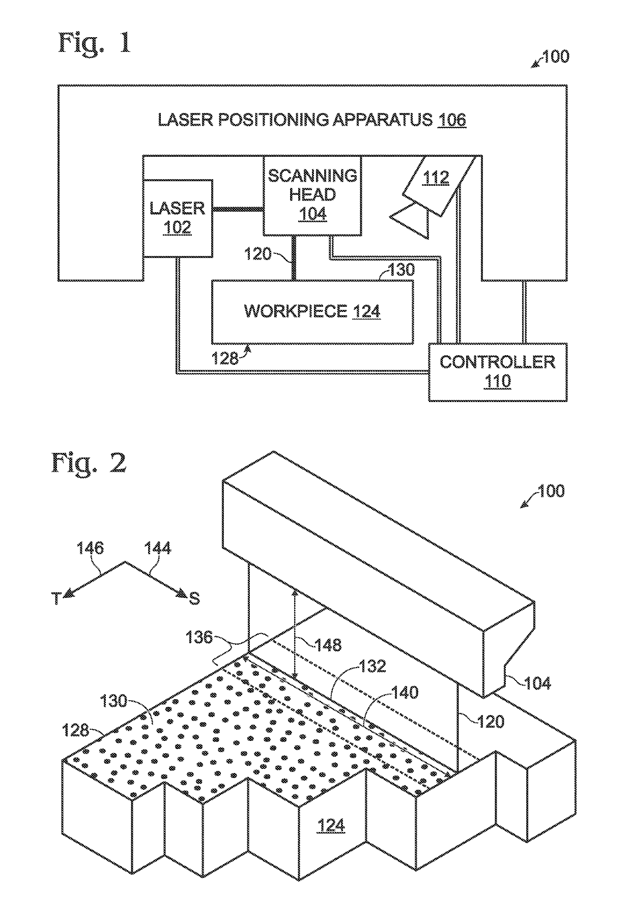
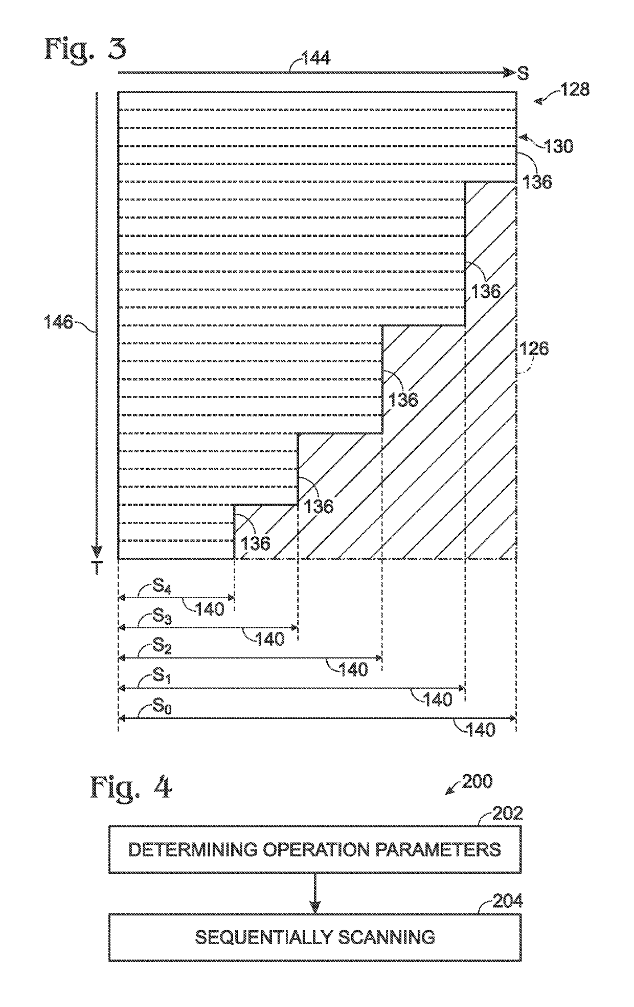
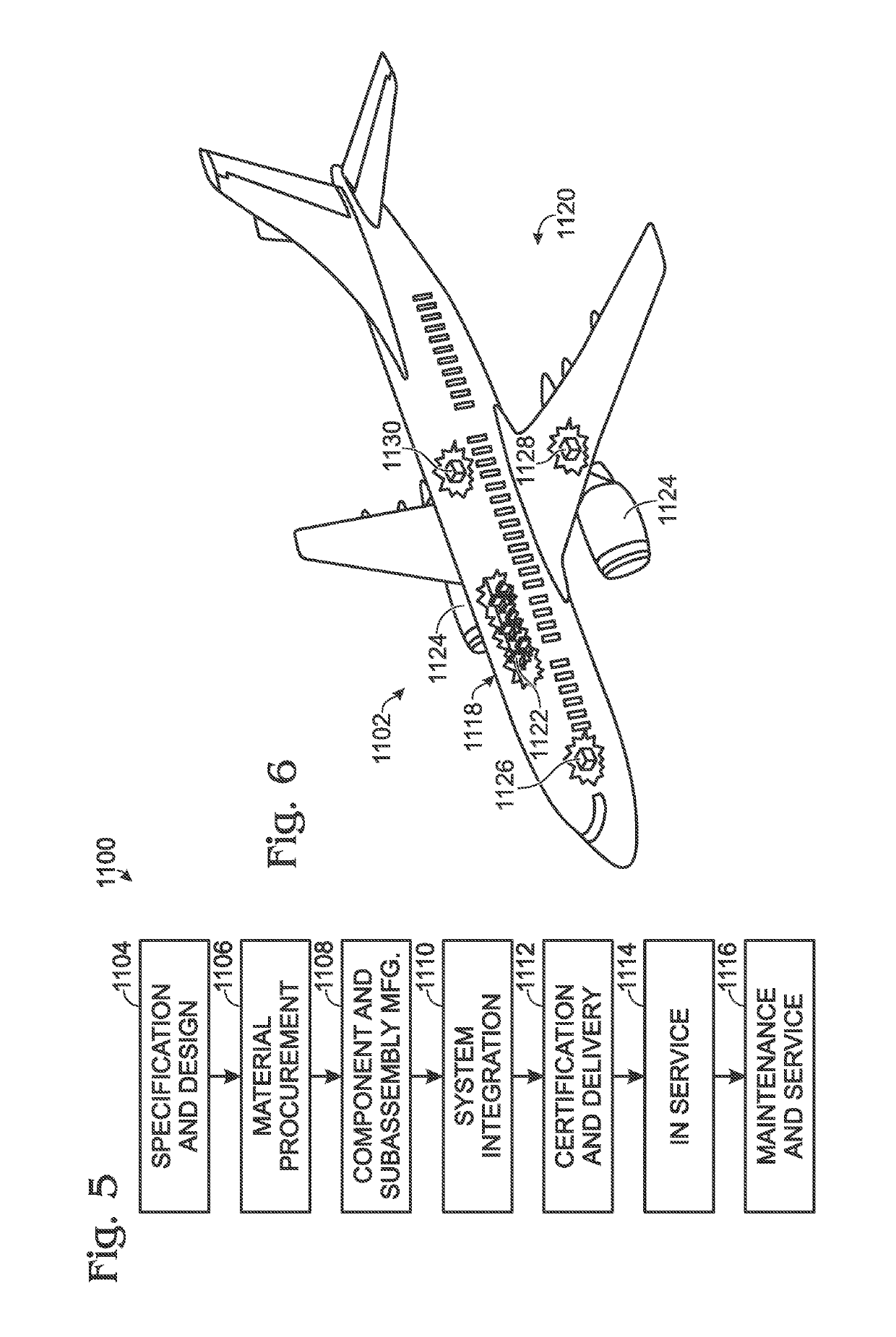
[0016]In FIGS. 1-6, referred to above, solid lines, if any, connecting various elements and / or components may represent mechanical, electrical, fluid, optical, electromagnetic and other couplings and / or combinations thereof. As used herein, “coupled” means associated directly as well as indirectly. For example, a member A may be directly associated with a member B, or may be indirectly associated therewith, e.g., via another member C. It will be understood that not all relationships among the various disclosed elements are necessarily represented. Accordingly, couplings other than those depicted in the block diagrams may also exist. Dashed lines, if any, connecting blocks designating the various elements and / or components represent couplings similar in function and purpose to those represented by solid lines; however, couplings represented by the dashed lines may either be selectively provided or may relate to alternative examples of the present disclosure. Likewise, elements and / or...


PUM

PropertyMeasurementUnit
Angleaaaaaaaaaa
Poweraaaaaaaaaa
Diameteraaaaaaaaaa

Abstract

A method of using a laser ablation system to clean an area of a surface with a laser beam, having a target fluence and a target irradiance. The area comprises scan regions, each having a scan width. The method comprises determining a traverse scan speed, a laser-beam average power, a laser pulse repetition rate, a laser pulse width, and a laser-beam spot area of the laser beam for each one of the scan regions to achieve the target fluence and the target irradiance. The scan width of at least one of the scan regions is different from the scan width of another one of the scan regions. The method also comprises sequentially scanning, across the scan width, each one of the scan regions of the area with the laser beam at the target fluence and the target irradiance.

Description

TECHNICAL FIELD[0001]The present disclosure relates to large-area selective ablation systems and methods.BACKGROUND[0002]Laser ablation is a method to clean or refresh surfaces. Contaminants or surface layers are ablated (destroyed) by applying laser energy directly to the surface. The laser is tuned to ablate the contaminants or surface layers while leaving the underlying surface material intact. The effectiveness of laser ablation is substantially due to the laser energy absorbed at the surface. If too much energy is absorbed, the surface may be damaged (over ablated). If too little energy is absorbed, the contaminants or surface layers may not be sufficiently affected (under ablated).[0003]In conventional laser ablation, the laser beam is scanned across the surface in a raster fashion. The laser beam is scanned quickly in one direction (the scan direction) and relatively slowly in another direction (the traverse direction). The laser beam generally is scanned so quickly in the sc...

Claims


Application Information

Patent Timeline
IPC IPC(8): B08B7/00B23K26/362B23K26/06B23K26/16B64F5/30B23K101/00
CPCB08B7/0042B23K26/0626B64F5/30B23K26/362B23K2101/006B23K26/082B23K26/354B23K26/36B23K26/361B23K26/16
Inventor BARCLAY, RICHARD CHARLES
Owner THE BOEING CO
Why Eureka
Try Eureka