
Systems and methods for environment sensing

a technology of environment sensing and system and method, applied in the field of system and method for environment sensing, can solve the problems of non-linear response, exponential, power law, non-monotonic response, and significant errors in chemical vapor concentration estimation of available conventional sensors

Active Publication Date: 2019-07-30
GENERAL ELECTRIC CO
View PDF50 Cites 5 Cited by
  • Summary
  • Abstract
  • Description
  • Claims
  • Application Information

AI Technical Summary

Benefits of technology

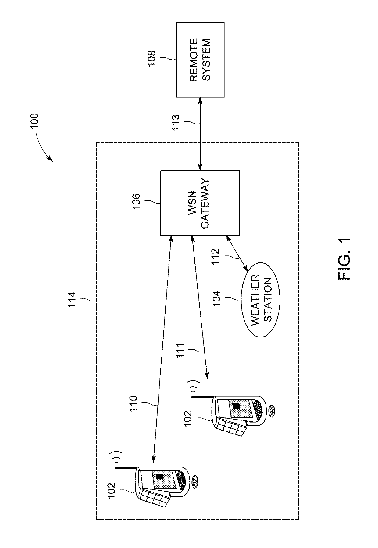
[0008]In an embodiment, a method (e.g., for detecting one or more analytes of interest) includes receiving a plurality of impedance responses and one or more ambient parameters from a plurality of sensor nodes. Each impedance response is representative of a sensing material of a sensor node in operational contact with an ambient environment. The method includes adjusting the plurality of impedance responses based on the one or more ambient parameters, and analyzing the plurality of impedance responses at frequencies that provide a linear response of the sensing material to an analyte of interest and at least partially reject effects of interferences.

Problems solved by technology

However, available conventional sensors suffer from a non-linear response, specifically an exponential, power law, and / or non-monotonic response, as a function of the chemical vapor concentration.
Due to the power law response, as the concentration of the chemical vapor increases, the chemical vapor saturates the conventional sensor response leading to significant errors in estimation of the chemical vapor concentration.
However, the sensor nodes within the conventional WSN are unable to measure multiple gases with individual sensors, reducing the reliability of the conventional WSN.
However, due to the plurality of conventional sensors for the sensor nodes, the sensor nodes demand a high power consumption, which restricts the type of power sources that can be utilized to power the node.
Further, the high power consumption reduces the lifetime of the sensor nodes within the conventional WSN.

Method used


Image

  • Systems and methods for environment sensing
  • Systems and methods for environment sensing
  • Systems and methods for environment sensing

Examples


Embodiment Construction

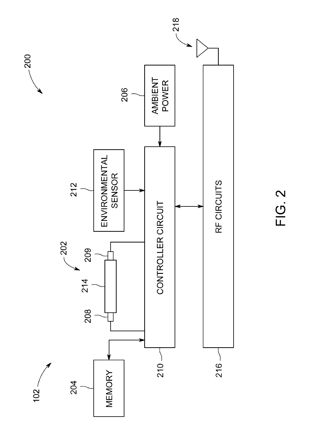
[0028]One or more embodiments herein describe systems and methods for environment sensing, specifically a wireless sensor network (WSN) having sensor nodes configured to detect one or more analytes of interest (e.g., methane gas, carbon monoxide gas, nitrogen oxide gas) within an environment. The sensor nodes include a sensor, such as a multivariable analyte sensor, and an environment sensor. The sensor may be similar to and / or the same as the sensor described in U.S. patent application entitled, “SYSTEMS AND METHODS FOR ENVIRONMENT SENSING” having Ser. No. 15 / 271,692, which is incorporated by reference in its entirety. The environment sensor may be configured to acquire ambient parameters of the environment (e.g., not the analytes of interest), such as ambient temperature, ambient relative humidity, ambient atmospheric pressure, meteorological conditions, light detection, wind direction, wind speed, and / or the like.

[0029]The sensor nodes are powered by an ambient power source (e.g....


PUM

PropertyMeasurementUnit
temperatureaaaaaaaaaa
frequencyaaaaaaaaaa

Abstract

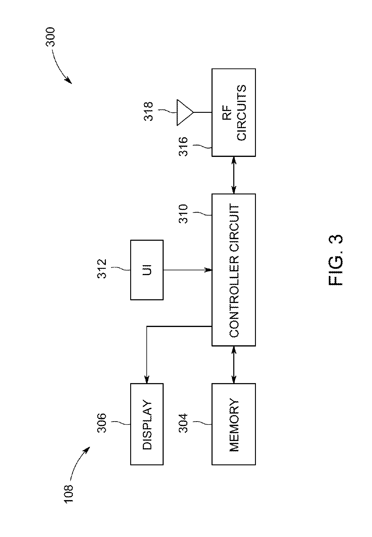
Systems and methods are provided for environment sensing. The system includes a sensor node having a sensor. The sensor includes a sensing material configured to be in contact with an ambient environment. The system includes a remote system having a communication circuit and a controller circuit. The communication circuit is configured to be wirelessly communicatively coupled to the sensor node. The controller circuit electrically coupled to the communication circuit. The controller circuit configured to receive an impedance response of the sensing material and analyze the impedance response of the sensing material at frequencies that provide a linear response of the sensing material to an analyte of interest and at least partially reject effects of interferences.

Description

FIELD[0001]Embodiments of the subject matter disclosed herein generally relate to systems and methods for environment sensing.BACKGROUND[0002]Environmental sensors, such as metal-oxide sensors, are often employed in a number of applications where the detection of various vapors or gases may be used to discern useful information. For example, environmental sensors may be utilized to monitor industrial areas for chemical or physical hazards, such as the detection of carbon dioxide within the chemical manufacturing industry, detection of engine exhaust gases such as carbon monoxide, hydrocarbons, and nitrogen oxides within the transportation industry, and detection of fugitive methane emissions within the oil and gas industry.[0003]One technique for sensing such environmental changes is by employing a conventional sensor, such as a radio frequency identification (RFID) sensor, a resistance sensor, and / or a capacitance sensor coated with a particular sensing material. The impedance, res...

Claims


Application Information

Patent Timeline
Patent Type & Authority Patents(United States)
IPC IPC(8): H04Q9/00G01W1/00G01N33/00
CPCH04Q9/00G01N33/0036G01W1/00H04Q2209/886H04Q2209/823H04Q2209/845H04Q2209/883H04Q2209/40
Inventor POTYRAILO, RADISLAV ALEXANDROVICHSEXTON, DANIEL WHITEGO, STEVEN
Owner GENERAL ELECTRIC CO
Learn More