
Gripper with spinning means

a technology of gripper and spinning means, which is applied in the field of gripper, can solve the problems of occupying a lot of space, consuming work time, and affecting the safety of workers, and achieves the effects of saving significant space in the gripper, reducing work time, and reducing work intensity

Active Publication Date: 2019-08-06
CANRIG ROBOTIC TECH AS
View PDF12 Cites 5 Cited by
  • Summary
  • Abstract
  • Description
  • Claims
  • Application Information

AI Technical Summary

Benefits of technology

Enables efficient, safe, and compact handling of pipe bodies with full rotational and translational freedom, reducing the need for multiple machines and cables, and allowing operation in explosion-exposed areas by using wireless power and communication, thereby improving safety and efficiency.

Problems solved by technology

Handling of pipe bodies, such as pipes and so-called subs, crossovers, kelly cocks, bottom hole assemblies, etc., may be a challenge on a rig floor.
The involvement of two different machines makes the work time consuming and the involvement of manual work together with heavy machinery is a potential safety risk.
Grippers with spinning means according to the prior art typically take up a lot of space and have a limited possibility of rotational and translational movement.
The gripping means and the spinning means are often driven via separate input shafts that take up space and limit the potential freedom of movement of the gripper.
Grippers according to the prior art are also typically provided with a plurality of cables, wires etc. to provide sufficient power and control of the gripper, such cables and wires are also limiting the freedom of movement and constituting a potential security risk in explosion-exposed areas, such as on a drilling rig.

Method used


Image

  • Gripper with spinning means
  • Gripper with spinning means
  • Gripper with spinning means

Examples


Embodiment Construction

[0058]In the following description, identical reference numerals refer to similar or identical features. The figures may be shown slightly simplified and schematic and the different features on the figures are not necessarily drawn to scale.

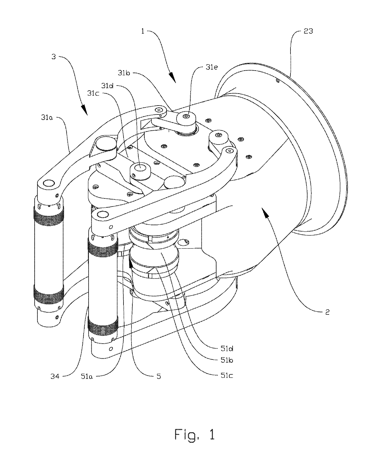
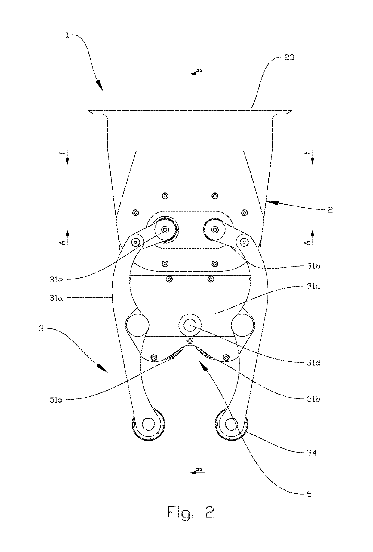
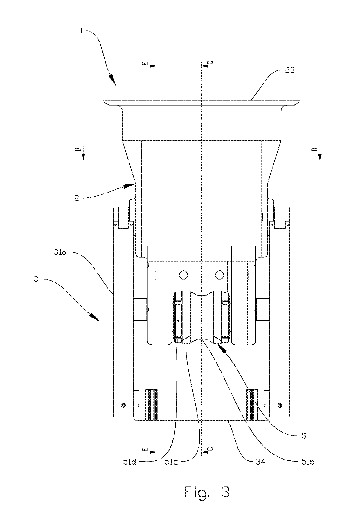
[0059]FIGS. 1-3 show a gripper 1 according to the present disclosure. The gripper 1 is provided with a housing 2, to which both gripping means 3 and spinning means 5 are connected. In a normal position of use, the housing 2 covers most of the parts constituting the gripper 1. These parts will be visible with reference to the following cross-sectional drawings. The gripping means 3 is provided in the form of two sets of gripping arms 31a. The gripping arms 31a are driven by drive arms 31b, rotatable around rotation axes 31e, and connected by link arms 31c, the link arms being connected to the gripper housing 2 at a rotation axis 31d. The functionality of the gripping means 3, which allows gripping of pipes and other objects of various diameters, w...


PUM


Abstract

A gripping device for gripping and spinning a pipe body of various diameters includes a gripping assembly having a pair of gripping arms for gripping the outer surface of the pipe body, and a spinning device having a pair of rollers for spinning the pipe body as it is engaged by gripping arms. The gripping device also includes a rotatable input shaft and a coupler. The coupler connects the rotatable input shaft to the gripping assembly and to the spinning device and is employed to selectively engage the gripping arms and the spinning device. A brake is provided so as to selectively prevent at least one of the gripping assembly and the spinning device from being operated upon rotating the rotatable input shaft.

Description

CROSS REFERENCE TO RELATED APPLICATIONS[0001]This application is the U.S. National Stage entry under 35 U.S.C. § 371 of International Patent Application No. PCT / NO2015 / 050232, filed Dec. 1, 2015, and entitled “Gripper with spinning means,” which claims priority to Application No. NO20141449, filed Dec. 2, 2014, all of which are hereby incorporated herein by reference in their entireties for all purposes.BACKGROUND[0002]Handling of pipe bodies, such as pipes and so-called subs, crossovers, kelly cocks, bottom hole assemblies, etc., may be a challenge on a rig floor. To connect or disconnect such pipe bodies from a pipe string it is today common to use a combination of manual work and machinery. One machine is typically used for lifting the pipe body while another machine is used to spin the pipe body so as to connect it to the drill string. The involvement of two different machines makes the work time consuming and the involvement of manual work together with heavy machinery is a pot...

Claims


Application Information

Patent Timeline
Patent Type & Authority Patents(United States)
IPC IPC(8): E21B19/16E21B19/14B25J19/00
CPCE21B19/161E21B19/168E21B19/14B25J19/0045B25J15/022B25J15/0004E21B19/164
Inventor SOYLAND, SVEINN.AE BUTTED.SGAAR, KJETIL
Owner CANRIG ROBOTIC TECH AS
Learn More