Catheter guiding system and methods

a guiding system and catheter technology, applied in the field of guiding systems, can solve the problems of increasing the time and cost of the procedure, increasing the risk of misalignment, increasing the cost of the overall procedure, and manipulating, so as to reduce the stress placed, the effect of spreading the stress

Active Publication Date: 2019-08-13
EVALVE
View PDF658 Cites 115 Cited by
  • Summary
  • Abstract
  • Description
  • Claims
  • Application Information

AI Technical Summary

Benefits of technology

[0012]Certain embodiments of the present disclosure include a guidance system for accessing a target area (e.g., mitral valve, tricuspid valve, other heart valve, or other heart tissue) within a body, the guidance system including a guidable catheter having a proximal end and a distal end, with a tip ring attached to the distal end. The tip ring has one or more saddles configured such that a pullwire passing through a pullwire channel in the tip ring can be looped over the saddle and back down through the pullwire channel or through another pullwire channel. When tension is applied to the pullwire, the pullwire engages against the saddle and thereby subjects the guidable catheter to a curving or steering force. The use of a saddle eliminates the need for a soldered or welded connection at the distal end of the catheter and is designed to reduce and / or spread the stresses placed on the pullwires at the distal connection over a larger surface area.
[0013]Certain embodiments include a tip ring having one or more indentations extending proximally from a distal edge of the tip ring, with a saddle being disposed within the indentation as a raised surface within the indentation. Certain embodiments include one or more saddles having a curved surface advantageous in preventing, reducing, and / or eliminating the formation of stress risers in a pullwire engaged against the saddle.

Problems solved by technology

Although such access reduces the need for traditional invasive surgery, challenges arise related to control, manipulation, and positioning of instruments near the target location, particularly within a target body cavity.
This increases the time and cost of the procedure and also the risk of misalignment.
This adds cost, complexity, and time to the overall procedure.
In any case, many of the same obstacles are encountered.
Such tailoring would be prohibitively complex and a single predicted curvature would most likely still require additional repositioning once inside the body.
Continuously replacing the single pre-shaped access catheter in hopes of obtaining the proper curvature would be expensive and time consuming, possibly placing the patient at additional risk.
Such steerability, basically the ability to form a single curvature, is generally inadequate for accessing and directing the catheter toward a target in a cavity.
However, the attachment of pullwires may fail when the pullwire is subjected to the forces required to steer or guide the catheter through the desired range of angles and curves.
Pullwires may be soldered or welded in place, thereby strengthening the connection to the catheter, but this adds to manufacturing time and costs, and may introduce hazardous chemicals necessitating additional cleanup and processing before the device can be suitably and safely introduced into the body.
Further still, a soldered or welded connection may result in a fairly rigid connection between the pullwire and the distal end of the catheter which may fail or break when placed under stress.
However, the use of stainless steel or other metal necessitates machining of the component, and expensive process adding to the manufacturing cost of the resulting device.
The adhesive bond between the machined, stainless steel key and the plastic catheter may fail, resulting in loss of the intended keying function.
Furthermore, the use of adhesives involves the use of additional chemicals and curing reaction products, and may require the expenditure of additional time and effort to prepare the catheter for safe introduction into the body.

Method used


Image

  • Catheter guiding system and methods
  • Catheter guiding system and methods
  • Catheter guiding system and methods

Examples


Embodiment Construction

I. Catheter Guiding System

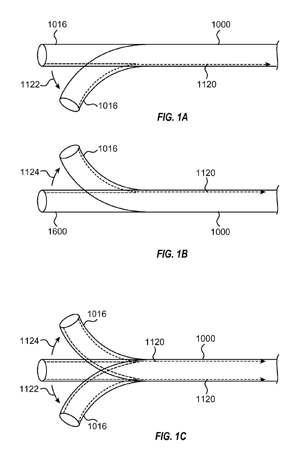
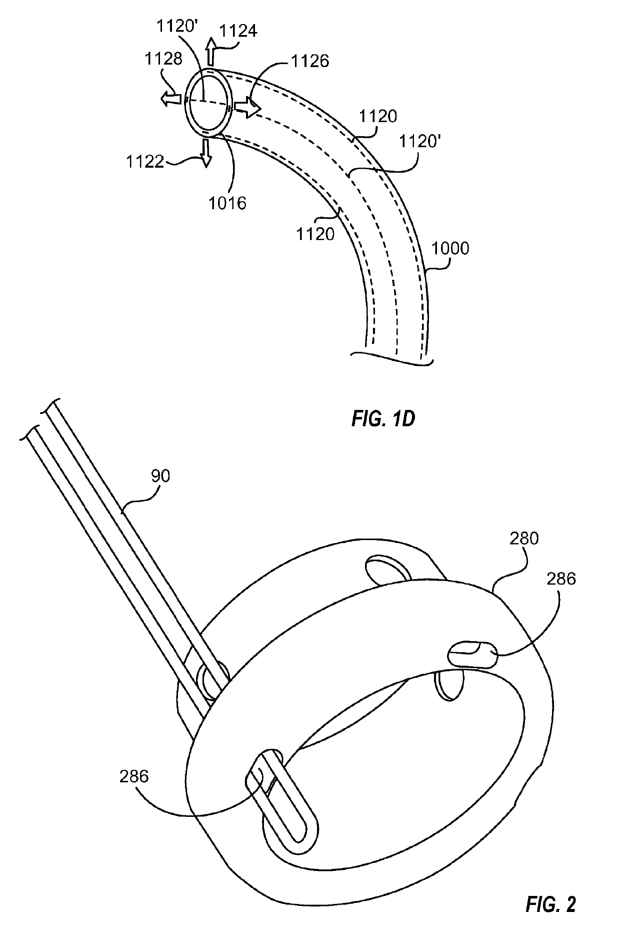
[0030]FIGS. 1A-1D illustrate embodiments of steerable guide catheters. To provide a higher degree of control and variety of possible curvatures, steering mechanisms may be used to create the curvatures and / or to position the catheters. In some embodiments, the steering mechanisms comprise cables or pullwires within the wall of the catheter. As shown in FIG. 1A, the guide catheter 1000 may include a pullwire 1120 slidably disposed in lumens within the wall of the catheter 1000 extending to the distal end 1016. By applying tension to the pullwire 1120 in the proximal direction, the distal end 1016 curves in the direction of the pullwire 1120 as illustrated by arrow 1122.

[0031]Likewise, as shown in FIG. 1B, placement of the pullwire 1120 along the opposite side of the catheter 1000 will allow the distal end 1016 to curve in the opposite direction, as illustrated by arrow 1124, when tension is applied to the pullwire 1120. Thus, referring to FIG. 1C, diametrica...


PUM


Abstract

A steerable guide catheter includes a tip ring at a distal end and one or more pullwires configured to engage with the tip ring when put in tension, the pullwire(s) thereby subjecting the steerable guide catheter to a curving or turning force. The tip ring includes a saddle and one or more pullwire channels allowing the pullwire to be looped over the saddle such that when the pullwire is placed under tension, it abuts against the saddle of the tip ring. Some embodiments include additional catheters axially aligned within or outside of the steerable guide catheter, and include a keying feature aligning the rotation of the multiple catheters. The keys of the keying feature can be formed of a polyamide with a glass microsphere filler, and can be thermally welded to the catheter.

Description

CROSS-REFERENCE TO RELATED APPLICATIONS[0001]N / ABACKGROUND[0002]The present invention relates to a guiding system for accessing a body cavity and directing the passage of devices therethrough into the cavity. Particularly, the present invention relates to a steerable catheter guiding system which directs the devices into the cavity in a desired orientation. In some embodiments, the present invention relates to endoluminally or transthoracically accessing an atrium of the heart to direct an interventional catheter toward a cardiac valve.[0003]To access a target location within the human body from a remote location, a catheter is typically passed through one or more body lumens, such as through the vascular system, to the target location. When the vascular system is used, the catheter is inserted into an artery or vein percutaneously or through a relatively small incision in the patient's body. The catheter is then threaded through the patient's system of blood vessels to reach the de...

Claims


Application Information

Patent Timeline
Patent Type & Authority Patents(United States)
IPC IPC(8): A61M25/01A61B17/128A61M25/00A61B17/00
CPCA61M25/0147A61B17/1285A61B2017/00243A61M2025/015A61B2017/00783A61M2025/0004A61B2017/00318A61F2/246
Inventor VAN HOVEN, DYLAN T.VITAL, JOSE C.LEE, AMY
Owner EVALVE
Why Eureka
Try Eureka