Dual mode hybrid hydrostatic driveline

a hybrid hydrostatic transmission and driveline technology, applied in the direction of hybrid vehicles, hybrid vehicles, hybrid vehicles, etc., can solve the problems of reduced vehicle performance, operator dissatisfaction, and torque interruptions in hybrid hydrostatic transmissions, so as to reduce torque interruptions, increase fuel efficiency of vehicles, and increase the range of operating speeds

Inactive Publication Date: 2019-08-13
DANA ITAL SPA
View PDF37 Cites 0 Cited by
  • Summary
  • Abstract
  • Description
  • Claims
  • Application Information

AI Technical Summary

Benefits of technology

[0006]Presently provided by the invention, a hybrid hydrostatic driveline and a method for shifting a powersplit transmission between modes of operation that minimizes torque interruption, increases a fuel efficiency of a vehicle, and increases a range of operating speeds of the vehicle the powersplit transmission is incorporated in, has surprisingly been discovered.
[0023]3. The hybrid driveline according to example 2, wherein the at least one control valve has at least a first position and a second position, the at least one control valve in the first position facilitating fluid communication between the high pressure accumulator and the first fluid conduit in fluid communication with the first hydrostatic unit and the at least one control valve in the second position facilitating fluid communication between the high pressure accumulator and the second fluid conduit in fluid communication with the first hydrostatic unit and the second hydrostatic unit.
[0025]5. The hybrid driveline according to example 1, wherein the clutching device comprises a shift collar, a first synchronizer, and a second synchronizer; the first synchronizer facilitating synchronization engagement between the first hydrostatic unit and the vehicle output and the second synchronizer facilitating synchronization between the second hydrostatic unit and the vehicle output.
[0026]6. The hybrid driveline according to example 1, wherein the clutching device comprises a first clutch and a second clutch; the first clutch facilitating variable driving engagement between the first hydrostatic unit and the vehicle output and the second clutch facilitating variable driving engagement between the second hydrostatic unit and the vehicle output.
[0029]9. The hybrid driveline according to example 8, wherein the clutching device comprises a first clutch, a second clutch, and a third clutch; the first clutch facilitating variable driving engagement between the first hydrostatic unit and the vehicle output, the second clutch facilitating variable driving engagement between the second hydrostatic unit and the vehicle output, and the third clutch facilitating variable driving engagement between the third hydrostatic unit and the vehicle output.
[0044]13. The method of operating a hybrid driveline for a vehicle in a hydrostatic drive mode and a direct drive mode according to example 12, further comprising the step of placing the at least one control valve in one of a first position and a second position, the at least one control valve in the first position facilitating fluid communication between the high pressure accumulator and the first fluid conduit in fluid communication with the first hydrostatic unit and the at least one control valve in the second position facilitating fluid communication between the high pressure accumulator and the second fluid conduit in fluid communication with the first hydrostatic unit and the second hydrostatic unit.

Problems solved by technology

Torque interruptions within the hybrid hydrostatic transmissions are strongly disfavored in the working cycle mode.
Vehicles which include such hybrid hydrostatic transmissions are also subject to torque interruptions during a shifting procedure between the working cycle mode and the transport cycle mode.
Such torque interruptions may result in reduced performance of the vehicle and operator dissatisfaction.

Method used


Image

  • Dual mode hybrid hydrostatic driveline
  • Dual mode hybrid hydrostatic driveline
  • Dual mode hybrid hydrostatic driveline

Examples


Embodiment Construction

[0066]It is to be understood that the invention may assume various alternative orientations and step sequences, except where expressly specified to the contrary. It is also to be understood that the specific devices and processes illustrated in the attached drawings, and described in the following specification are simply exemplary embodiments of the inventive concepts defined herein. Hence, specific dimensions, directions or other physical characteristics relating to the embodiments disclosed are not to be considered as limiting, unless expressly stated otherwise.

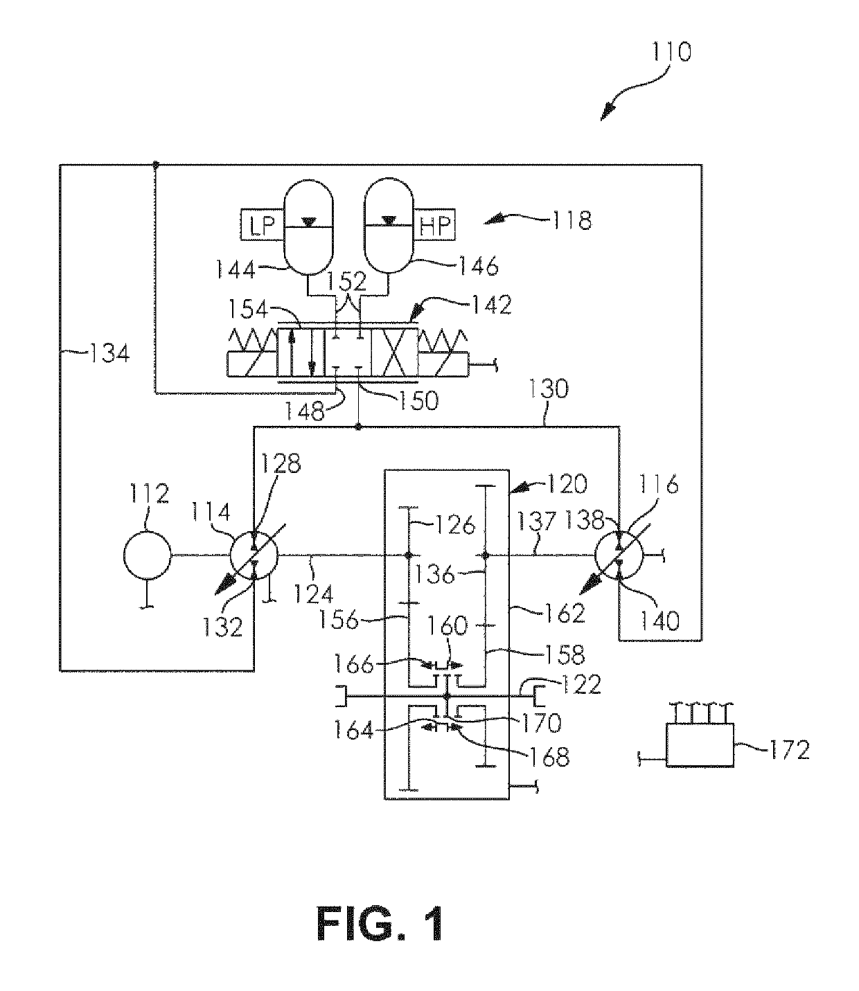
[0067]FIG. 1 schematically illustrates a driveline 110 for a vehicle (not shown). The driveline 110 comprises a power source 112, a first hydrostatic unit 114, a second hydrostatic unit 116, an accumulator assembly 118, and a clutching device 120. The first hydrostatic unit 114 is drivingly engaged with the power source 112 and the clutching device 120. The second hydrostatic unit 116 is drivingly engaged with the clutchin...


PUM


Abstract

A hybrid driveline which may be operated in a hydrostatic drive mode and a direct drive mode and a method of operating a hybrid driveline in a hydrostatic drive mode and a direct drive mode is provided. The hybrid driveline comprises a power source, a first hydrostatic unit drivingly engaged with the power source, a second hydrostatic unit selectively drivingly engaged with a vehicle output and in fluid communication with the first hydrostatic unit, an accumulator assembly in fluid communication with the first hydrostatic unit and the second hydrostatic unit, and a clutching device selectively drivingly engaged with the vehicle output and one of the first hydrostatic unit and the second hydrostatic unit. The hybrid driveline provides the benefits of a series hybrid arrangement and a parallel hybrid arrangement, reduces torque interruptions during operation and shifting procedures, and increases an efficiency of a vehicle the driveline is incorporated in.

Description

FIELD OF THE INVENTION[0001]The present invention generally relates to power transmission systems. More particularly, this invention relates to a hybrid hydrostatic transmission for a vehicle, in which the hybrid hydrostatic transmission may be operated in a hydrostatic power transmission mode or a direct drive power transmission mode.BACKGROUND OF THE INVENTION[0002]Vehicles that incorporate hybrid hydrostatic transmissions, such as earth moving machinery, industrial equipment, and others are typically referred to as having a series hybrid arrangement or a parallel hybrid arrangement. In the series hybrid arrangement, at least one accumulator and a control valve are used to collect energy from or deliver stored energy to a conventional hydrostatic transmission, which includes a first hydrostatic unit drivingly engaged with a power source and a second hydrostatic unit drivingly engaged with a transmission output. In the parallel hybrid arrangement, at least one accumulator and a con...

Claims


Application Information

Patent Timeline
Patent Type & Authority Patents(United States)
IPC IPC(8): B60K6/12B60W10/02B60K17/02B60K17/10B60K6/442
CPCB60K6/12B60K6/442B60K17/02B60W10/02B60K17/10Y02T10/6282Y02T10/6208Y02T10/6234Y02T10/62B60K6/38
Inventor ORNELLA, GIULIOSERRAO, LORENZO
Owner DANA ITAL SPA
Why Eureka
Try Eureka