Control device for internal combustion engine

a control device and internal combustion engine technology, applied in the direction of electrical control, machine/engine, electric control of exhaust, etc., can solve the problems of inability to remove unburned gas contained in exhaust, and achieve the effect of suppressing deterioration of exhaust emission

Inactive Publication Date: 2019-08-13
TOYOTA JIDOSHA KK
View PDF9 Cites 2 Cited by
  • Summary
  • Abstract
  • Description
  • Claims
  • Application Information

AI Technical Summary

Benefits of technology

[0006]The present disclosure was made focusing on this problem and has as its object to suppress the deterioration of the exhaust emission occurring when the oxygen storage amount of the second catalyst is not sufficient.
[0008]According to this aspect of the present disclosure, it is possible to suitably restore the oxygen storage amount of the second catalyst, so it is possible to suppress deterioration of the exhaust emission occurring in the case where the oxygen storage amount of the second catalyst is not sufficient.

Problems solved by technology

As a result, the target air-fuel ratio is switched to the rich air-fuel ratio before the oxygen storage amount of the second catalyst is sufficiently restored, so when rich air-fuel ratio exhaust flows out from the first catalyst, the unburned gas contained in the exhaust cannot be removed by oxidation by the second catalyst and the exhaust emission is liable to deteriorate.

Method used


Image

  • Control device for internal combustion engine
  • Control device for internal combustion engine
  • Control device for internal combustion engine

Examples


first embodiment

Explanation of Internal Combustion Engine as a Whole

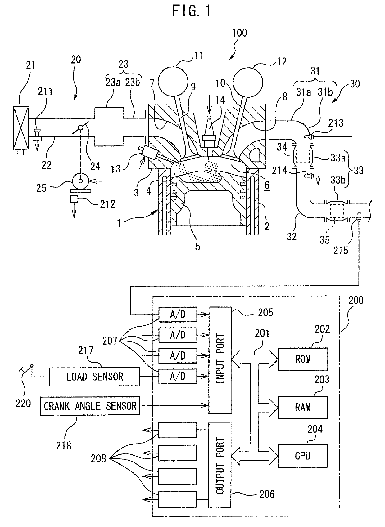
[0022]First, referring to FIG. 1 to FIG. 5, an internal combustion engine 100 and an electronic control unit 200 controlling the internal combustion engine 100 according to a first embodiment of the present invention will be explained. FIG. 1 is a view of the general configuration of the internal combustion engine 100 and the electronic control unit 200 controlling the internal combustion engine 100 according to an embodiment of the present invention.

[0023]As shown in FIG. 1, the internal combustion engine 100 is provided with an engine body 1, intake device 20, and exhaust device 30.

[0024]The engine body 1 is provided with a cylinder block 2 and a cylinder head 3 fixed to the top surface of the cylinder block 2.

[0025]The cylinder block 2 is formed with a plurality of cylinders 4. Inside of the cylinders 4, pistons 5 which receive the combustion pressure and move back and forth inside of the cylinders 4 are housed. The pistons 5 ar...

second embodiment

[0167]Next, a second embodiment of the present invention will be explained. The present embodiment differs in content of control for restoration of the storage amount from the first embodiment. Specifically, it differs from the first embodiment in the point of performing lean failure control during control for restoration of the storage amount to make the second oxygen storage amount OSAufc increase in stages. Below, this will be explained focusing on this point of difference.

[0168]In the above-mentioned first embodiment, after switching the target air-fuel ratio to the third lean air-fuel ratio AFL3, the target air-fuel ratio was maintained at the third lean air-fuel ratio AFL3 until the second oxygen storage amount OSAufc became the resumption reference amount Crefdwn or more. That is, in the above-mentioned first embodiment, to restore the oxygen storage amount of the second three-way catalyst 35, lean air-fuel ratio exhaust containing NOX was made to continuously flow into the s...


PUM


Abstract

A control device for an internal combustion engine is provided with a target air-fuel ratio setting part including a first setting control part performing normal control alternately switching a target air-fuel ratio between a predetermined first lean air-fuel ratio and a predetermined first rich air-fuel ratio and a second setting control part performing control for restoration of the storage amount stopping normal control and increasing the oxygen storage amount of a second catalyst when an output air-fuel ratio of a third air-fuel ratio sensor becomes a predetermined rich judgment air-fuel ratio or less. Further, the second setting control part is configured to set the target air-fuel ratio to a predetermined second lean air-fuel ratio larger than the first lean air-fuel ratio at the time of start of the control for restoration of the storage amount and set the target air-fuel ratio to a predetermined third lean air-fuel ratio smaller than the second lean air-fuel ratio after an exhaust with a larger air-fuel ratio than the stoichiometric air-fuel ratio flows out from the first catalyst in the time period of setting the target air-fuel ratio to the second lean air-fuel ratio.

Description

CROSS-REFERENCE TO RELATED APPLICATION[0001]This application claims priority based on Japanese Patent Application No. 2016-134235 filed with the Japan Patent Office on Jul. 6, 2016, the entire contents of which are incorporated into the present specification by reference.TECHNICAL FIELD[0002]The present disclosure relates to a control device for an internal combustion engine.BACKGROUND ART[0003]JP2005-299430A discloses an internal combustion engine comprising a first catalyst arranged in an exhaust passage of an engine body and having an oxygen storage ability, a second catalyst arranged in the exhaust passage at the downstream side from the first catalyst and having an oxygen storage ability, a first exhaust sensor (air-fuel ratio sensor) arranged at an upstream side of the first catalyst, a second exhaust sensor (oxygen sensor) arranged between the first catalyst and the second catalyst, and a third exhaust sensor (oxygen sensor) arranged at the downstream side of the second catal...

Claims


Application Information

Patent Timeline
Patent Type & Authority Patents(United States)
IPC IPC(8): F02D41/14F01N3/28F02D41/02F01N11/00F01N9/00
CPCF02D41/1454F01N3/2892F01N9/00F01N11/007F02D41/0295F02D41/1441F02D41/1475F02D41/1445Y02T10/47F01N2430/06F01N2560/025F01N2560/14F01N2900/1624F02D2200/0814Y02T10/40
Inventor INOSHITA, KENJIOKAZAKI, SHUNTAROMIYOSHI, YUJI
Owner TOYOTA JIDOSHA KK
Why Eureka
Try Eureka