
Single-chip high-magnetic-field X-axis linear magnetoresistive sensor with calibration and initialization coil

a high-magnetic field, linear technology, applied in the field of single-chip high-magnetic field x-axis linear magnetoresistive sensor with calibration and initialization coil, can solve the problems of sensor change resistance, sensor low magnetic field sensitivity, sensor relatively low magnetoresistance and thus poor sensitivity, etc., to achieve precise regulation of the magnitude of the calibration magnetic field and improve the efficiency of measurement. effect of precision

Active Publication Date: 2019-08-13
MULTIDIMENSION TECH CO LTD
View PDF14 Cites 0 Cited by
  • Summary
  • Abstract
  • Description
  • Claims
  • Application Information

AI Technical Summary

Benefits of technology

[0007]The present invention proposes a single-chip high-magnetic-field X-axis linear magnetoresistive sensor with a calibration and an initialization coil. A calibration and an initialization coil are introduced onto a chip, a suitable current passes through the calibration coil, a calibration magnetic field is generated along an X direction respectively at positions of a magnetoresistive sensing unit string and a reference magnetoresistive unit string, and precise regulation on the magnitude of the calibration magnetic field is achieved by regulating a calibration current. Because the calibration coil is located on the X-axis sensor chip, during measurement, only a quick measurement is required while applying the calibration current, thus improving the efficiency precision of the measurement.
[0008]Similarly, when irreversible changes of magnetization state occur in the X-axis magnetoresistive sensor under the action of an external magnetic field, a current may be introduced into the initialization coil, external magnetic fields along initial magnetization directions of free layers are generated at the locations of all the magnetoresistive sensor units, thus restoring magnetization states of the free layers, to eliminate historical influences on the magnetization states of soft magnetic films due to the effect of the magnetic field.
[0012]During calibration, a calibration current passes through the calibration coil, such that an X-direction sensing unit calibration magnetic field and a reference unit calibration magnetic field are generated respectively at the locations of the sensing magnetoresistive sensor unit string and the reference magnetoresistive sensor unit string, and a calibration function is performed by measuring an output signal of the X-axis magnetoresistive sensor; during initialization, an initialization current passes through the initialization coil, and an initialization magnetic field is generated along a Y direction at the location of each magnetoresistive sensor unit, thus restoring the magnetic state of the magnetoresistive sensor units.

Problems solved by technology

The advantage thereof is the Hall sensor can measure a relatively wide range of magnetic fields, but a disadvantage thereof is the sensor has low magnetic field sensitivity, and it is generally necessary to introduce a flux concentrator to amplify an external magnetic field.
The advantage is the sensor units are simple and only have one layer of film, but a disadvantage is the sensor has a relatively low magnetoresistance and thus poor sensitivity.
Then the current that tunnels between the ferromagnetic free layer and the reference layer changes, resulting in a change of resistance of the sensor.

Method used

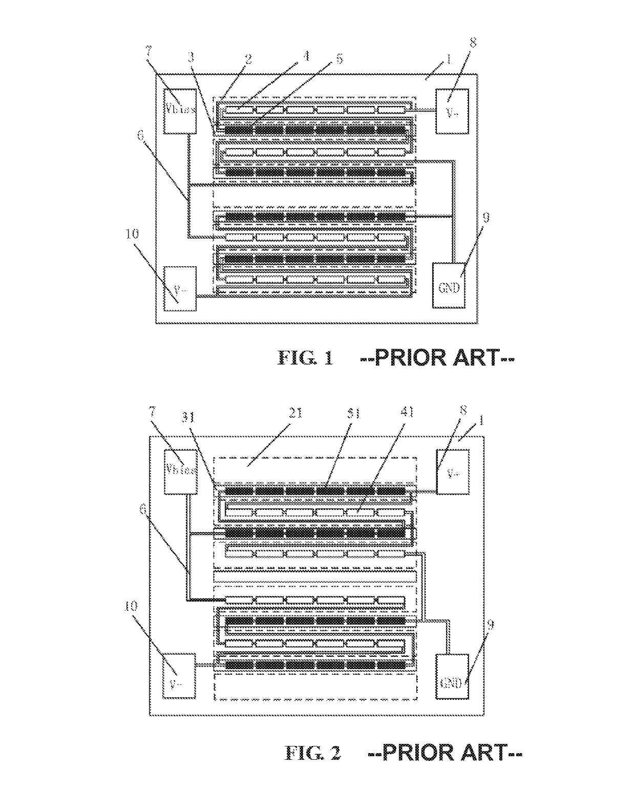

Image

  • Single-chip high-magnetic-field X-axis linear magnetoresistive sensor with calibration and initialization coil
  • Single-chip high-magnetic-field X-axis linear magnetoresistive sensor with calibration and initialization coil
  • Single-chip high-magnetic-field X-axis linear magnetoresistive sensor with calibration and initialization coil

Examples


embodiment 1

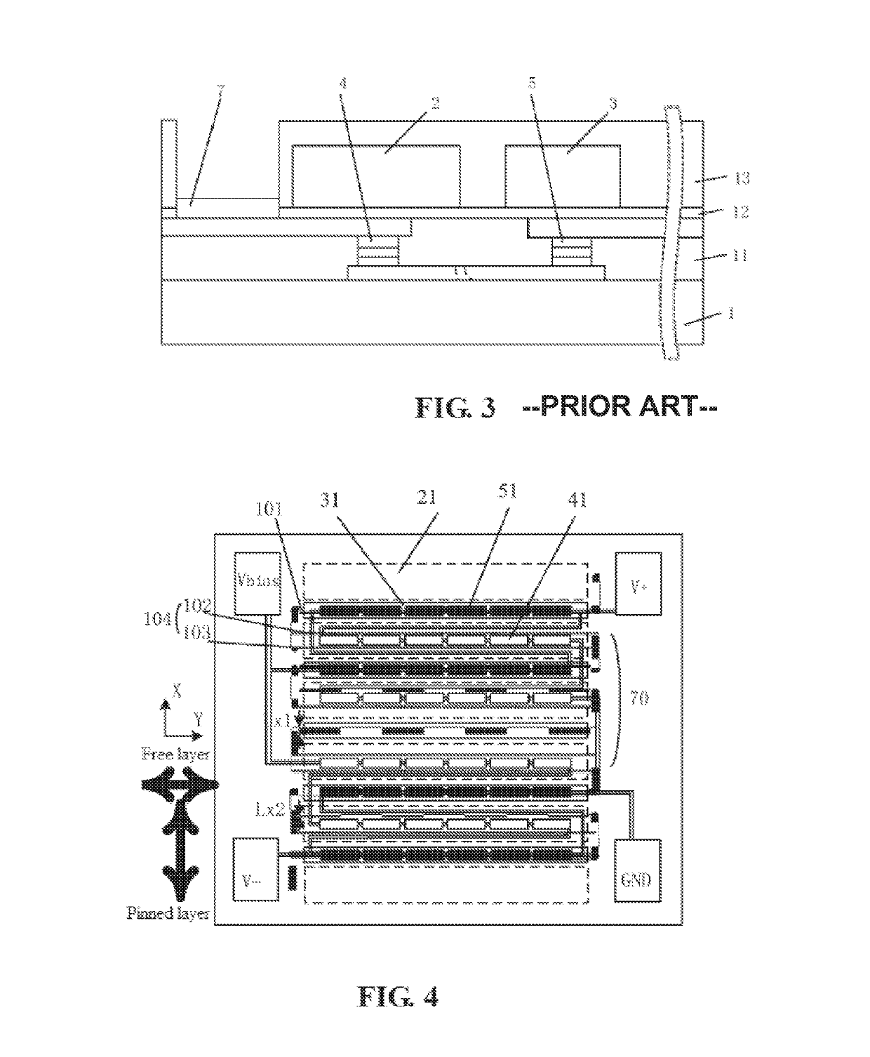
[0067]FIG. 4 is a diagram of structure and distribution of a first type of calibration coils 70. The calibration coils 70 are planar coils, including elongated sensing unit straight wires 101 and reference unit straight wires 104 connected in series. The sensing unit straight wires 101 have a width of Lx1, and Y-axis center lines thereof are arranged along a sensing magnetoresistive sensor unit string 51. Each of the reference unit straight wires 104 includes two straight sub-wires 102 and 103. The straight sub-wires 102 and 103 are connected in parallel and are symmetrically distributed, along the Y direction, on two sides of the reference magnetoresistive sensor unit string 41. The straight sub-wires 102 and 103 both have a width of Lx2.

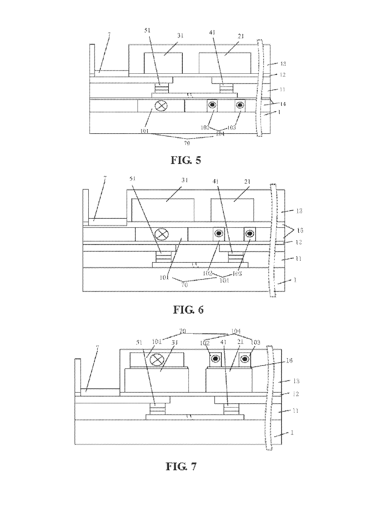
[0068]FIGS. 5-7 are sectional views of an X-axis magnetoresistive sensor including a first type of calibration coils 70 shown in FIG. 4 respectively. In FIG. 5, the planar calibration coils are placed above the substrate 1 and below the magnetoresi...

embodiment 2

[0076]FIG. 14 is a structural diagram of planar calibration coils of a second type 80 on a high magnetic field single-chip X-axis linear magnetoresistive sensor. The second type of planar calibration coils 80 include two straight wires, i.e., a reference unit straight wire 105 and a sensing unit straight wire 106, which are respectively placed at gaps between the shielding device 21 and the attenuator 31. Moreover, the reference unit straight wire 105 has a larger width and is placed on one side close to the shielding device 21. The sensing unit straight wire 106 has a smaller width and is placed on one side close to the attenuator 31, and the sensing unit straight wire 106 and the reference unit straight wire 105 are mutually connected in series.

[0077]FIG. 15 is a sectional view of planar calibration coils of a second type 80 on a high magnetic field single-chip X-axis linear magnetoresistive sensor, wherein the reference unit straight wire 105 and the sensing unit straight wire 10...

embodiment 3

[0080]FIG. 19 is a diagram of distribution of planar calibration coils of a third type 81 on a high magnetic field single-chip X-axis magnetoresistive sensor. The third type of planar calibration coils 81 include a sensing unit straight wire 107 and a reference unit straight wire 108 connected in series, wherein the reference unit straight wire 108 corresponds to the shielding device 21, the sensing unit straight wire 107 corresponds to the attenuator 31, the reference unit straight wire 108 and the sensing unit straight wire 107 are both elongated, which coincide with Y-axis center lines of the attenuator 31 and the shielding device 21 respectively, and the width of the sensing unit straight wire 107 is less than that of the reference unit straight wire 108.

[0081]FIG. 20 is a sectional view of planar calibration coils of a third type 81 on a high magnetic field single-chip X-axis magnetoresistive sensor. The reference unit straight wire 108 and the sensing unit straight wire 107 ar...


PUM


Abstract

A single-chip high-magnetic-field X-axis linear magnetoresistive sensor with a calibration and an initialization coil, comprising a high magnetic field single-chip referenced bridge X-axis magnetoresistive sensor, a calibration coil, and an initialization coil, wherein the calibration coils are planar coils, and the initialization coils are planar or three-dimensional coils. The planar calibration coils and the planar initialization coils can be placed above a substrate and below the magnetoresistive sensor units, between the magnetoresistive sensor units and the soft ferromagnetic flux guides, above the soft ferromagnetic flux guides, or at gaps between the soft ferromagnetic flux guides. The three-dimensional initialization coil is wound around the soft ferromagnetic flux guides and magnetoresistive sensor units. The calibration coils and the initialization coils generate a calibration magnetic field paralleled the direction of pinned layer and a uniform initialization magnetic field in the direction of the free layer respectively at the location of the magnetoresistive sensor units. Through controlling the current of the calibration coils and the initialization coils, the calibration and initialization of the magnetic state of the single-chip X-axis linear magnetoresistive sensor can be performed.

Description

PRIORITY CLAIM TO RELATED APPLICATIONS[0001]This application is a U.S. national stage application filed under 35 U.S.C. § 371 from International Application Serial No. PCT / CN2016 / 073244, which was filed 3 Feb. 2016, and published as WO2016 / 124135 on 11 Aug. 2016, and which claims priority to Chinese Application No. 201510056576.4, filed 4 Feb. 2015, which applications and publication are incorporated by reference as if reproduced herein and made a part hereof in their entirety, and the benefit of priority of each of which is claimed herein.TECHNICAL FIELD[0002]The present invention relates to the field of magnetic sensors, and in particular, to a single-chip high-magnetic-field X-axis linear magnetoresistive sensor with a calibration and an initialization coil.BACKGROUND ART[0003]Silicon magnetic sensors mainly include Hall sensors, AMR sensors, and GMR sensors. With respect to the Hall sensor, a semiconductor film, such as indium telluride, is deposited on a substrate and the path ...

Claims


Application Information

Patent Timeline
Patent Type & Authority Patents(United States)
IPC IPC(8): G01R33/00G01R33/09
CPCG01R33/098G01R33/09G01R33/0017G01R33/0011G01R33/0094G01R33/0076
Inventor DEAK, JAMES GEZAZHOU, ZHIMIN
Owner MULTIDIMENSION TECH CO LTD
Learn More