Optical see-through display element and device utilizing such element

a display element and optical technology, applied in the field of optical devices, can solve the problems of low white balance over the entire field of view of display elements with out-coupling gratings, and achieve the effect of high image quality and increased coupling efficiency

Active Publication Date: 2019-08-13
DISPELIX OY
View PDF28 Cites 7 Cited by
  • Summary
  • Abstract
  • Description
  • Claims
  • Application Information

AI Technical Summary

Benefits of technology

[0012]It is an aim of the invention to provide a see-through optical display element, i.e. combiner element, which has an increased coupling efficiency for the image displayed on the display. A further aim is to combine this advantage with minor side effects and a high image quality.

Problems solved by technology

Display elements with an out-coupling grating typically also suffer from low white balance over the entire field of view.

Method used


Image

  • Optical see-through display element and device utilizing such element
  • Optical see-through display element and device utilizing such element
  • Optical see-through display element and device utilizing such element

Examples


Embodiment Construction

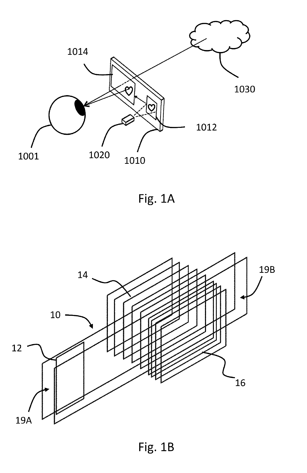
[0055]FIG. 1A shows an optical see-through display element 1010 comprising an in-coupling grating 1012 and an out-coupling grating 1014. There is also a projector 1020 directed at the in-coupling grating 1012, which diffracts the incident light to such angles that light propagates in the element 1010 via total internal reflections towards the out-coupling grating 1014. When the diffracted light reach the out-coupling grating 1014, it is diffracted towards the eye of an observer 1001 where the final image pattern is formed on the retina. Simultaneously to seeing the image pattern, the observer sees through the element 1010 any objects 1030 behind it.

[0056]FIG. 1B shows a display element according to one embodiment in more detail. The element comprises a substrate 10 (defined by the large rectangles). The substrate 10 is made of material which can act as a wave guide for at least some wavelengths of visible light, i.e. conduct light within the substrate 10 laterally. The substrate 10 ...


PUM


Abstract

An optical see-through display element and a display device using such an element. The element having a transparent substrate including two opposite faces, an in-coupling structure for coupling light into the substrate, and a diffractive out-coupling grating structure arranged on the transparent substrate for displaying the in-coupled light on the transparent substrate. The diffractive out-coupling structure includes at least two multi-layer gratings superimposed on top of each other on at least one of said opposite faces of the substrate. In particular, multilayer gratings reducing diffraction of transmissive light can be used. The element and device help to increase the out-coupling efficiency of diffractive displays and provides also technology to simultaneously maintain high image quality and transparency.

Description

FIELD OF THE INVENTION[0001]The invention relates to optical devices. In particular, the invention relates to see-through display elements that can be used in head-up displays (HUDs), near-to-eye displays (NEDs), head-mounted displays (HMDs) and so-called augmented reality glasses or smart glasses, for example.BACKGROUND OF THE INVENTION[0002]See-through displays comprise three fundamental parts: an image projector, a computing unit controlling the projector, and an optical combiner which is adapted to show the image from the projector to a see-through display, which allows the user of the display to see both the scenery behind the display and the projected image without requiring the user to look away from his usual viewpoint. In a diffractive grating based see-through display solutions image is coupled from an in-coupling grating into a waveguide. From the waveguide the image is coupled out to the eye of a user by an out-coupling grating. Several examples of devices operating with...

Claims


Application Information

Patent Timeline
Patent Type & Authority Patents(United States)
IPC IPC(8): G02B5/18G02B27/01G02B6/00F21V8/00G02B27/00
CPCG02B27/0172G02B5/1814G02B5/1823G02B6/00G02B6/0016G02B6/0038G02B27/0103G02B27/0081G02B2027/0178G02B2027/0107G02B2027/0116G02B2027/0118G02B2027/0123
Inventor OLKKONEN, JUUSOSUNNARI, ANTTI
Owner DISPELIX OY
Why Eureka
Try Eureka