Electronic sphygmomanometer for measuring blood pressure and pulse

a technology of sphygmomanometer and pulse, which is applied in the field of electromechanical sphygmomanometer and a measuring method of blood pressure and pulse, can solve the problems of no longer detecting the change in the volume of the artery, and the artery gradually reduces, so as to reduce the burden on the patien

Active Publication Date: 2019-08-27
OMRON HEALTHCARE CO LTD
View PDF19 Cites 1 Cited by
  • Summary
  • Abstract
  • Description
  • Claims
  • Application Information

AI Technical Summary

Benefits of technology

[0014]Therefore, one or more embodiments of the present invention provide a measuring device and measuring method that can measure pulse rate and blood pressure value accurately for an extended period of time while reducing the burden on a patient.

Problems solved by technology

Further, the change in the volume of the artery is gradually larger in proportion to the inflation of the cuff by compression due to the dynamic characteristics of the artery in this arrangement, and after the maximum value is exceeded, it gradually reduces, and when the artery is compressed and closed, the change in the volume of the artery is no longer detected.

Method used


Image

  • Electronic sphygmomanometer for measuring blood pressure and pulse
  • Electronic sphygmomanometer for measuring blood pressure and pulse
  • Electronic sphygmomanometer for measuring blood pressure and pulse

Examples


Embodiment Construction

[0035]Embodiments of the present invention will be described hereinafter with reference to drawings. In the following descriptions, the same reference numerals are assigned to the same parts and configuration elements. Those terms and functions are also the same.

Configuration of the Device

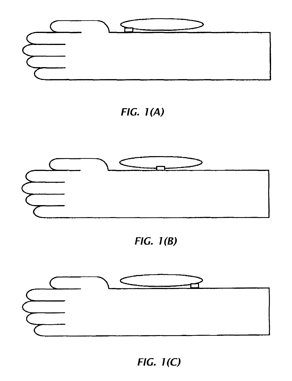
[0036]FIG. 6 is a block diagram illustrating a specific example of a device configuration of an electronic sphygmomanometer (hereinafter referred to as the sphygmomanometer) as a measurement device in accordance with one or more embodiments of the present invention. The sphygmomanometer 1 is used for measuring blood pressure variation for an extended period of time. Therefore, as described above, it is assumed that a wrist sphygmomanometer in which a cuff (air bladder) is mounted on the wrist is used here. However, the sphygmomanometer is not limited to only being mounted to the wrist, and the sphygmomanometer is also able to be mounted on other locations of the four limbs such as an upper arm, an ...


PUM


Abstract

An electronic sphygmomanometer includes a cuff including an air bladder, a pressure sensor, an artery volume sensor, and a computation device. The computation device includes an inner pressure control section, a volume sensor signal receive section for receiving a pulse wave signal detected by the artery volume sensor, a pressure sensor signal receive section for receiving a pressure pulse wave signal superimposed on the inner pressure of the air bladder and detected by the pressure sensor, a judgment section for choosing either the pulse wave signal or the pressure pulse wave signal as a signal for calculating pulse rate of the patient during a period when the inner pressure of the air bladder is increased and / or decreased by the inner pressure control section, and a pulse rate calculation section for calculating pulse rate of the patient based on the pulse wave signal and the signal chosen by the judgment section.

Description

BACKGROUND OF THE INVENTION[0001]1. Field of the Invention[0002]The present invention relates to an electronic sphygmomanometer and a measuring method for blood pressure and pulse using the electronic sphygmomanometer, and particularly relates to a measuring device for measuring blood pressure and pulse by using a cuff and a method thereof.[0003]2. Description of the Related Art[0004]In the past, sphygmomanometers in which a cuff (air bladder) is mounted on a measurement location such as a wrist or an upper arm, and blood pressure is calculated from cuff pressure fluctuation that is transmitted from an artery, have become popular. As the sphygmomanometer used for measuring the blood pressure variation for an extended period of time, the wrist sphygmomanometer in which a cuff is mounted on the wrist may reduce the burden on a patient compared to that in which the cuff is mounted on an upper arm. It could be said that the radial artery at the wrist is a better suited location for meas...

Claims


Application Information

Patent Timeline
Patent Type & Authority Patents(United States)
IPC IPC(8): A61B5/02A61B5/00A61B5/024A61B5/0235A61B5/022A61B5/021A61B5/0215A61B5/0225
CPCA61B5/024A61B5/02422A61B5/02225A61B5/6824A61B5/02A61B5/02158A61B5/02208A61B5/022A61B5/0225A61B5/021A61B5/02108A61B5/02233A61B5/0235A61B5/7278A61B5/742
Inventor UMEDA, SHOTASAWANOI, YUKIYAMATSUMURA, NAOMIKITAGAWA, TSUYOSHI
Owner OMRON HEALTHCARE CO LTD
Why Eureka
Try Eureka