Pulse transmission time measuring apparatus and biological state estimating apparatus

a technology of transmission time and measuring apparatus, which is applied in the field of pulse transmission time measuring apparatus and biological state estimation apparatus, can solve the problems of difficult to obtain continuous measurement of pulse wave velocity during activities and relatively poor ease of use, and achieve the effect of convenient attachment to the body and easy attachment to the body

Active Publication Date: 2019-08-27
MURATA MFG CO LTD
View PDF26 Cites 26 Cited by
  • Summary
  • Abstract
  • Description
  • Claims
  • Application Information

AI Technical Summary

Benefits of technology

[0010]Preferred embodiments of the present invention provide a pulse transmission time measuring apparatus that allows for easier attachment to the body and enables continuous measurement of pulse transmission time during activities, and a biological state estimating apparatus including the pulse transmission time measuring apparatus.

Problems solved by technology

This makes it difficult to obtain continuous measurement of pulse wave velocity during activities (for example, during daily life).
Further, the attachment of the apparatus is cumbersome as described above, resulting in relatively poor ease of use.

Method used


Image

  • Pulse transmission time measuring apparatus and biological state estimating apparatus
  • Pulse transmission time measuring apparatus and biological state estimating apparatus
  • Pulse transmission time measuring apparatus and biological state estimating apparatus

Examples


first modification

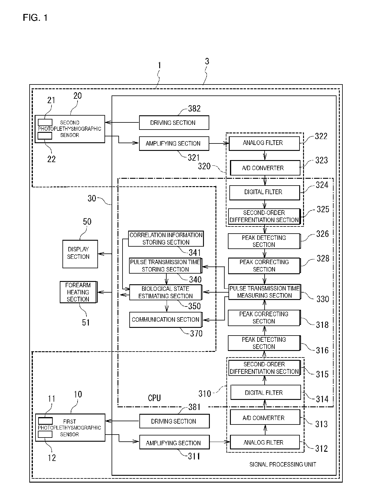
[0162]In the preferred embodiment of the present invention described above, the first photoplethysmographic sensor 10 including the first light emitter 11 and the first light receiver 12, and the second photoplethysmographic sensor 20 including the second light emitter 21 and the second light receiver 22 are used to respectively detect the first and second photoplethysmographic signals. Alternatively, as illustrated in FIG. 8, the first light emitter 11 and the second light emitter 21 may be made common (that is, shared by the first photoplethysmographic sensor 10 and the second photoplethysmographic sensor 20). FIG. 8 is a block diagram illustrating the configuration of a biological state estimating apparatus 3B including a pulse transmission time measuring apparatus 1B according to a first modification of a preferred embodiment of the present invention. In FIG. 8, components identical or equivalent to those in the preferred embodiment mentioned above are denoted by the same refere...

second modification

[0168]In the preferred embodiments of the present invention mentioned above, the first photoplethysmographic sensor 10 including the first light emitter 11 and the first light receiver 12, and the second photoplethysmographic sensor 20 including the second light emitter 21 and the second light receiver 22 are used to respectively detect the first and second photoplethysmographic signals. Alternatively, as illustrated in FIG. 9, the first light receiver 12 and the second light receiver 22 may be made common (that is, shared by the first photoplethysmographic sensor 10 and the second photoplethysmographic sensor 20). FIG. 9 is a block diagram illustrating the configuration of a biological state estimating apparatus 3C including a pulse transmission time measuring apparatus 1C according to a second modification. In FIG. 9, components identical or equivalent to those in the preferred embodiments mentioned above are denoted by the same reference signs. In this case, components such as an...

third modification

[0174]In the preferred embodiment mentioned above, the first photoplethysmographic sensor 10 including the first light emitter 11 and the first light receiver 12 is used to detect the first photoplethysmographic signal corresponding to the flow of blood in the radial artery. Alternatively, as illustrated in FIG. 10, a piezoelectric pulse wave sensor 13 that includes a piezoelectric element 14 and detects a piezoelectric pulse wave signal may be used instead of the first photoplethysmographic sensor 10. FIG. 10 is a block diagram illustrating the configuration of a biological state estimating apparatus 3D including a pulse transmission time measuring apparatus 1D according to a third modification of a preferred embodiment of the present invention. In FIG. 10, components identical or equivalent to those in the preferred embodiments of the present invention described above are denoted by the same reference signs.

[0175]In the pulse transmission time measuring apparatus 1D according to t...


PUM


Abstract

A pulse transmission time measuring apparatus includes a first photoplethysmographic sensor that includes a first light emitter and a first light receiver and detects a first photoplethysmographic signal, and a second photoplethysmographic sensor that includes a second light emitter and a second light receiver and detects a second photoplethysmographic signal. The first and second photoplethysmographic sensors are disposed on a contact surface that comes into contact with the body when the pulse transmission time measuring apparatus is attached to the body. The spacing between the second light emitter and the second light receiver is smaller than the spacing between the first light emitter and the first light receiver. The second photoplethysmographic sensor detects the second photoplethysmographic signal corresponding to the flow of blood in the capillaries. The first photoplethysmographic sensor detects the first photoplethysmographic signal corresponding to the flow of blood in an artery located deeper than the capillaries and thicker than the capillaries.

Description

CROSS REFERENCE TO RELATED APPLICATIONS[0001]This application claims the benefit of priority to Japanese Patent Application 2014-083234 filed Apr. 14, 2014 and is a Continuation Application of PCT / JP2015 / 059887 filed on Mar. 30, 2015. The entire contents of each of these applications are hereby incorporated herein by reference.BACKGROUND OF THE INVENTION[0002]1. Field of the Invention[0003]The present invention relates to a pulse transmission time measuring apparatus that measures pulse transmission time, and a biological state estimating apparatus including the pulse transmission time measuring apparatus.[0004]2. Description of the Related Art[0005]Pulse wave velocity measuring apparatuses are known in the art to measure pulse wave velocity (or pulse transmission time) as information related to values such as the rate and time of propagation of a pulse wave in the arteries of a living body. The pulse wave velocity represents information related to the rate at which a pulse wave pro...

Claims


Application Information

Patent Timeline
Patent Type & Authority Patents(United States)
IPC IPC(8): A61B5/024A61B5/0245A61B5/026A61B5/00A61M21/02A61M21/00
CPCA61B5/02433A61B5/02438A61B5/0245A61B5/0261A61B5/681A61B5/7246A61B5/7278A61B2562/0238A61B2562/043A61M21/02A61M2021/0066A61M2205/3306A61M2209/088A61M2230/06A61M2230/005A61M2205/3303
Inventor SHIMUTA, TORU
Owner MURATA MFG CO LTD
Why Eureka
Try Eureka