Air supply plenum

a technology of air supply and plenum, which is applied in the direction of air intakes for fuel, machines/engines, transportation and packaging, etc., can solve the problems of over-all loss of engine performance, excess fuel consumption, and increase the hourly cost of helicopter use, so as to reduce the impact of the phenomenon and increase the engine performance

Active Publication Date: 2019-08-27
SAFRAN HELICOPTER ENGINES
View PDF6 Cites 0 Cited by
  • Summary
  • Abstract
  • Description
  • Claims
  • Application Information

AI Technical Summary

Benefits of technology

[0006]A general aim of the invention is to propose an air supply plenum which makes it possible to increase performance of the engine by reducing the impact of the phenomenon of the formation of aerodynamic separation.

Problems solved by technology

Current engines, and more particularly helicopter engines, encounter a problem with creating aerodynamic separation at the air supply plenum of the engine, upstream of the air intake of the engine.
This aerodynamic loss at the air intake 2 of the engine brings about an overall loss of performance in the engine.
Such a solution leads to excess fuel consumption and to a surcharge for the helicopter, this increasing the hourly cost for use of the helicopter.

Method used


Image

  • Air supply plenum
  • Air supply plenum
  • Air supply plenum

Examples


Embodiment Construction

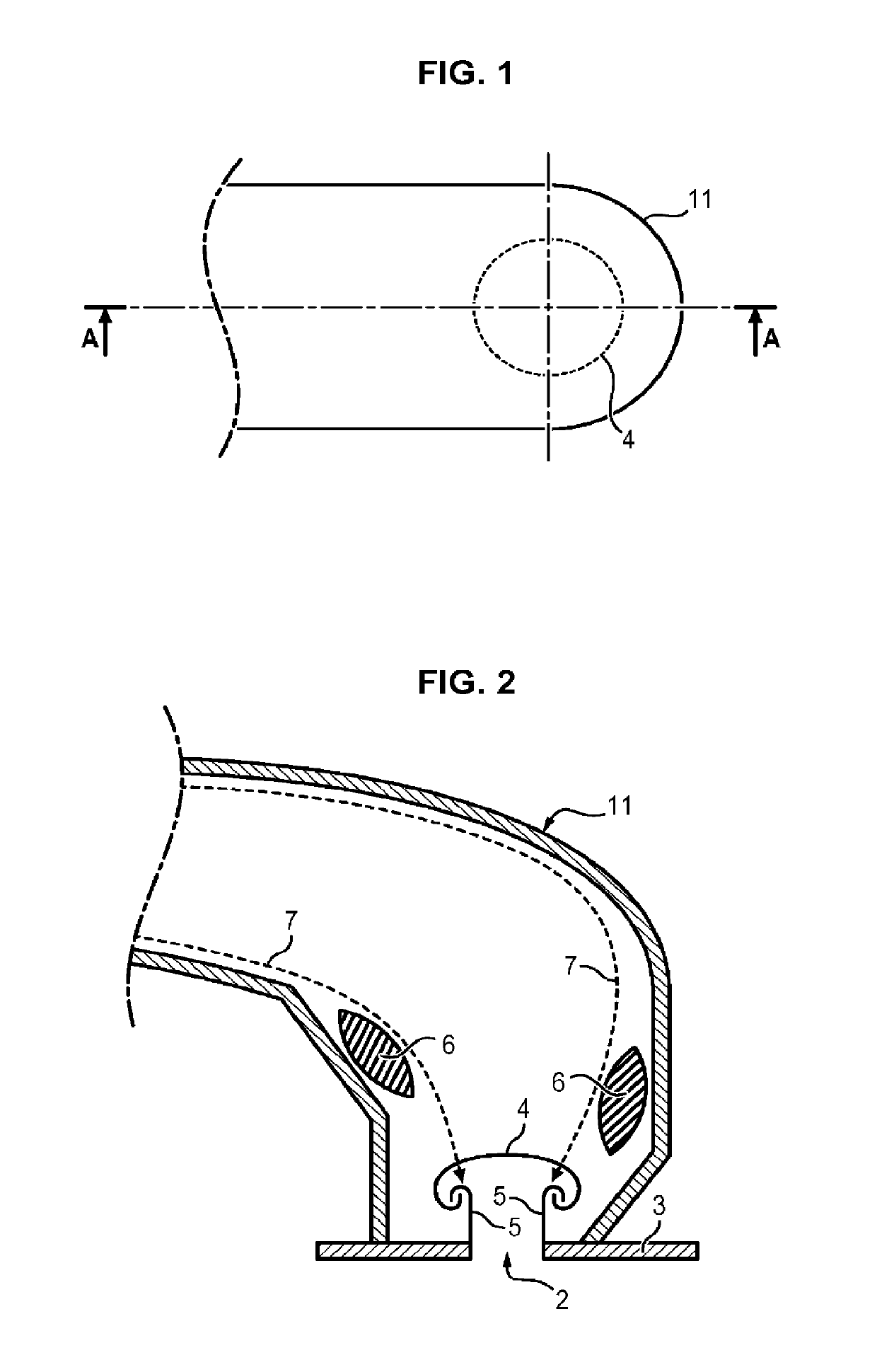
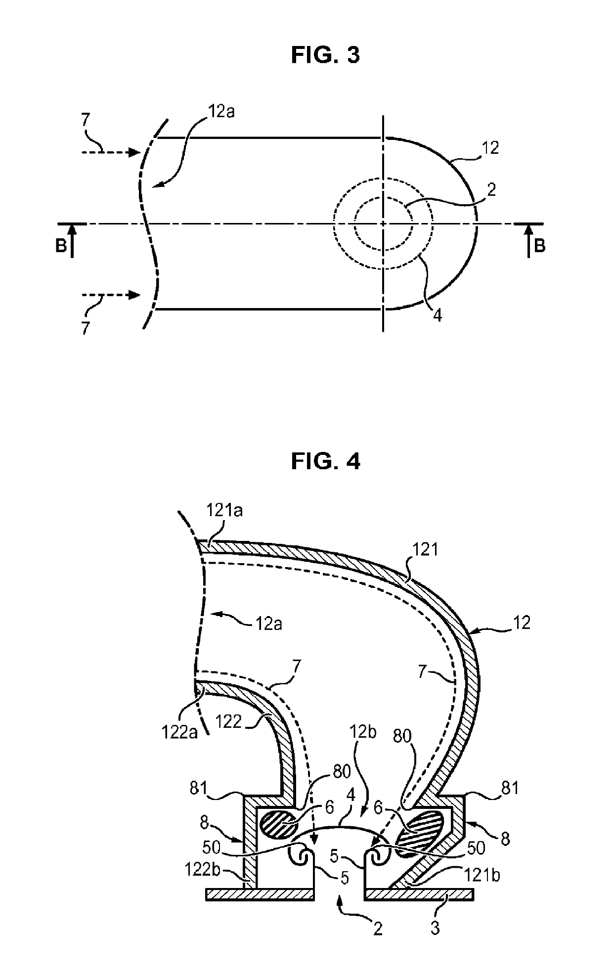
[0024]Shown in FIG. 3, is an air supply plenum 12 of a helicopter engine which is positioned at an air intake 2 of said helicopter engine.

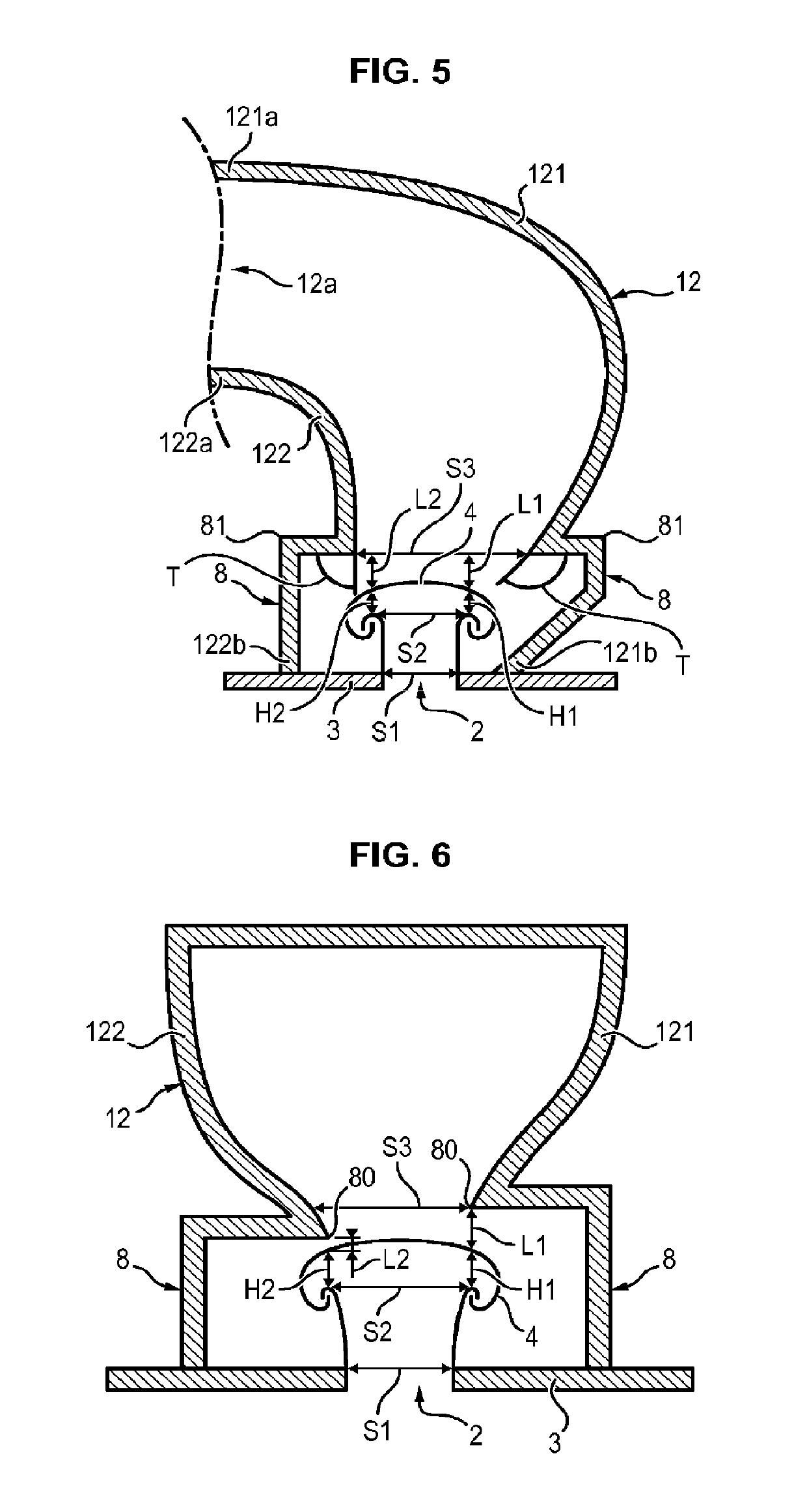
[0025]As shown in FIG. 4, the plenum 12 comprises a first lateral wall 121 and a second lateral wall 122 which form together a conduit guiding an air flow 7 coming from the outside toward the air intake 2 of the engine.

[0026]The two lateral walls 121 and 122 each comprise two ends 121a, 121b and 122a, 122b. The first ends 121a, 122a of the two lateral walls 121 and 122 form a first end 12a of the air supply plenum 12 through which the air flow 7 penetrates into said air supply plenum 12. The second ends 121b and 122b of the two lateral walls 121 and 122 form a second end 12b of the plenum 12 through which the air flow 7 penetrates into the air intake 2 of the engine.

[0027]The engine comprises a casing 3 wherein the air intake 2 of the engine is provided. The casing 3 comprises lips 5 which project inside the conduit formed by the air supply plenum...


PUM


Abstract

An air supply plenum for an engine, the plenum being disposed upstream of an air intake of the engine, the air intake being provided in a casing of the engine. The air supply plenum includes a first lateral wall and a second lateral wall which together form a conduit in which an air flow flows as the engine functions. Each lateral wall includes a step which forms a transverse recess relative to the direction of the air flow in the air supply plenum, such that an aerodynamic separation occurs in the step when the engine is operating.

Description

[0001]The present invention relates to the air supply plenum of an engine.[0002]More precisely, it relates to a particular form of the air supply plenum of a helicopter engine.GENERAL TECHNICAL FIELD AND PRIOR ART[0003]Current engines, and more particularly helicopter engines, encounter a problem with creating aerodynamic separation at the air supply plenum of the engine, upstream of the air intake of the engine.[0004]An air supply plenum according to the prior art, which is positioned at an air intake 2 of the engine, is shown in FIG. 1 and FIG. 2. The air intake 2 of the engine is provided in a casing 3 of the engine. A grid 4 is positioned at the air intake 2 of said engine. In order to maintain this grid 4 in position at the air intake of the engine, the air intake 2 comprises lips 5 directed toward the outside of the engine, and on which the grid is positioned. Due in particular to the presence of these lips 5, aerodynamic separation 6 occur which reduce the width of the air fl...

Claims


Application Information

Patent Timeline
Patent Type & Authority Patents(United States)
IPC IPC(8): F02M35/10F15D1/02F02C7/055B64D33/02
CPCB64D33/02F02C7/055F05D2220/329F05D2250/511B64D2033/0246F02M35/10B64C27/04B64D2033/022B64D2033/0226F15D1/02
Inventor BULOT, NICOLASMARCHAND, FABRICE
Owner SAFRAN HELICOPTER ENGINES
Why Eureka
Try Eureka