
Diagnostic device and method for monitoring frictional behavior in a control loop

a technology of friction behavior and diagnostic device, which is applied in the direction of flow control using electric means, testing/monitoring control systems, instruments, etc., can solve the problems of slippage in the valve, impair the accuracy and control quality of the control loop, and increase the friction in the valve, so as to achieve reliable estimated values and reduce computing capacity requirements

Active Publication Date: 2019-08-27
SIEMENS AG
View PDF17 Cites 0 Cited by
  • Summary
  • Abstract
  • Description
  • Claims
  • Application Information

AI Technical Summary

Benefits of technology

The present invention provides a diagnostic device and method for accurately estimating the friction in a valve using data from a control loop monitoring. This allows for improved control quality and increased productivity and efficiency of the plant without affecting the process operation. The estimation is performed using a low computing capacity and can be done in real-time. The method uses a quantitative estimation of the Hammerstein model, which is a linear submodel of the non-invasive diagnosis. A search space enclosed by two parameters of the nonlinear submodel is divided into a plurality of adjacent subspaces to reduce computing complexity. Each parameter pair obtained in the subspace can now be used with comparatively low computing complexity to determine the parameter pair with the best quality in the entire search space.

Problems solved by technology

The most common cause of problems and faults in control loops of this kind is increased friction in the valve, which can be caused by ageing of the seal, coatings on the seal or valve stem or due to packing gland seals that have been excessively tightened.
Increased valve friction can impair the accuracy and control quality of the control loop.
This results from the slip friction in the valve.
Methods for the identification of stiction provide binary information on its presence, but are not always reliable.
However, there are no specific suggestions as to which method should be given preference for control loop monitoring.
In order to estimate the intensity of the impacts of the frictional influences, the aforementioned book describes two methods involving a similar procedure under the heading “Stiction Estimation”, but both of these require very high computing complexity.
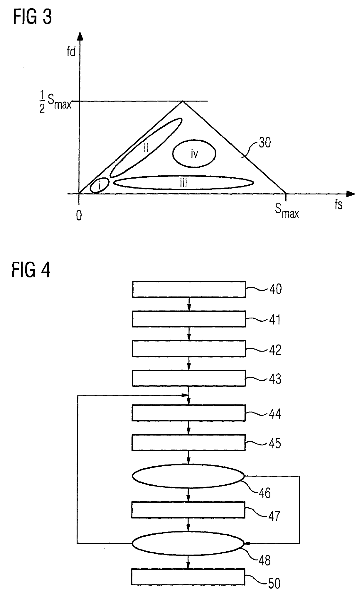
This entails an optimization problem with the two parameters fs and fd.
The practical implementation of the method named therein can also give rise to several problems:
A discrete-time least-squares estimation can entail various numerical problems, such as in connection with measuring noise or the choice of sampling interval, which complicate the estimation of the optimal parameters.
No previous findings are available with respect to the path dynamics and no suitable discrete-time model type is selected.

Method used


Image

  • Diagnostic device and method for monitoring frictional behavior in a control loop
  • Diagnostic device and method for monitoring frictional behavior in a control loop
  • Diagnostic device and method for monitoring frictional behavior in a control loop

Examples


Embodiment Construction

[0051]The same parts are given the same reference characters in the figures.

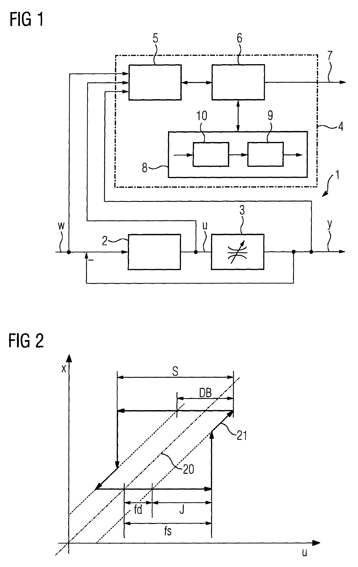
[0052]With reference to FIG. 1, a control loop 1 to be monitored consists of a controller 2 and a process 3, which is frequently also called a controlled system, and comprises a valve as an actuator. The control loop 1 can, for example, be a flow controller. In this case, the setpoint w is specified for a flow value, which is to be set via the valve. An actual value y is acquired at the output of the process 3 and fed back to form a control deviation. The controller 2 uses the control deviation to calculate a manipulated variable u to set the flow at the process 3. The manipulated variable u can, for example, directly entail the specification of a desired valve setting.

[0053]If, unlike the case in the exemplary embodiment depicted, the control loop is a position regulator, the setpoint is a positional setting and the actual value corresponds directly to the position of the valve used in the process.

[0054]A d...


PUM


Abstract

A diagnostic device and diagnostic method for monitoring the operation of a control loop with a controlled system having a valve as an actuator, wherein in the case of a substantially stepped profile of a setpoint, a linear submodel is identified, which is subsequently used, with a substantially constant setpoint, in order to identify a nonlinear submodel, which is arranged upstream of the linear submodel in a Hammerstein model for the controlled system so as to facilitate a quantitative assessment of the friction behavior of a valve with a comparatively low level of computing complexity.

Description

BACKGROUND OF THE INVENTION[0001]1. Field of the Invention[0002]The invention relates to a diagnostic device and method for monitoring the operation of a control loop having a controlled system comprising a valve as an actuator.[0003]2. Description of the Related Art[0004]The maintenance and servicing of automated plants can be improved by monitoring the correct functioning of plant segments or components. In the case of insufficient reliability, measures for maintenance, servicing and fault correction can be targeted at the correct place in the plant. In numerous control loops in industrial plants, valves are used as actuators in controlled systems. The most common cause of problems and faults in control loops of this kind is increased friction in the valve, which can be caused by ageing of the seal, coatings on the seal or valve stem or due to packing gland seals that have been excessively tightened. Increased valve friction can impair the accuracy and control quality of the contr...

Claims


Application Information

Patent Timeline
Patent Type & Authority Patents(United States)
IPC IPC(8): G05D7/06G05B17/02G05B23/02
CPCG05B23/0213G05B17/02G05B23/0254G05D7/06
Inventor HEILER, PATRICKPFEIFFER, BERND-MARKUS
Owner SIEMENS AG
Learn More