Metal plate and metal cover employing same

a metal plate and metal cover technology, applied in the field of corrugated metal plates, can solve the problems of increased cost, significant strength difference, increased work volume, etc., and achieve the effect of minimizing the difference of flexural rigidity, reducing the number of working operations, and high second moment of area

Active Publication Date: 2019-09-03
NISSAN MOTOR CO LTD +2
View PDF21 Cites 2 Cited by
  • Summary
  • Abstract
  • Description
  • Claims
  • Application Information

AI Technical Summary

Benefits of technology

[0010]The present invention was made in view of the above-mentioned task. In particular, it provides a metal plate and a metal cover, in which a corrugation or embossing work for forming both of cross-sectional shapes into a wave shape is easy, and which are usable irrespective of directional property by minimizing the difference of flexural rigidity between the two directions.
[0013]According to the metal plate of the present invention, both of cross-sectional shapes along two directions, that is, their respective rows' direction of the row having a shape of a projection and a recess and a direction intersecting the same are in a corrugated shape. Therefore, not only it is high in second moment of area and is improved in surface rigidity, but also it is possible to minimize the difference of flexural rigidity in the two directions. For example, even in the case of producing a heat insulation cover or the like by forming into a predetermined three-dimensional product shape, the directional property does not matter, and the corrugated metal plate becomes superior in usability.

Problems solved by technology

Thus, it is forced to have an increased cost by an increase of the number of working operations.
However, the difference of rigidity against bending between X-direction and Y-direction tends to result in a significant strength difference.
As a result, the corrugated metal plate is not superior in usability.

Method used


Image

  • Metal plate and metal cover employing same
  • Metal plate and metal cover employing same
  • Metal plate and metal cover employing same

Examples


first embodiment

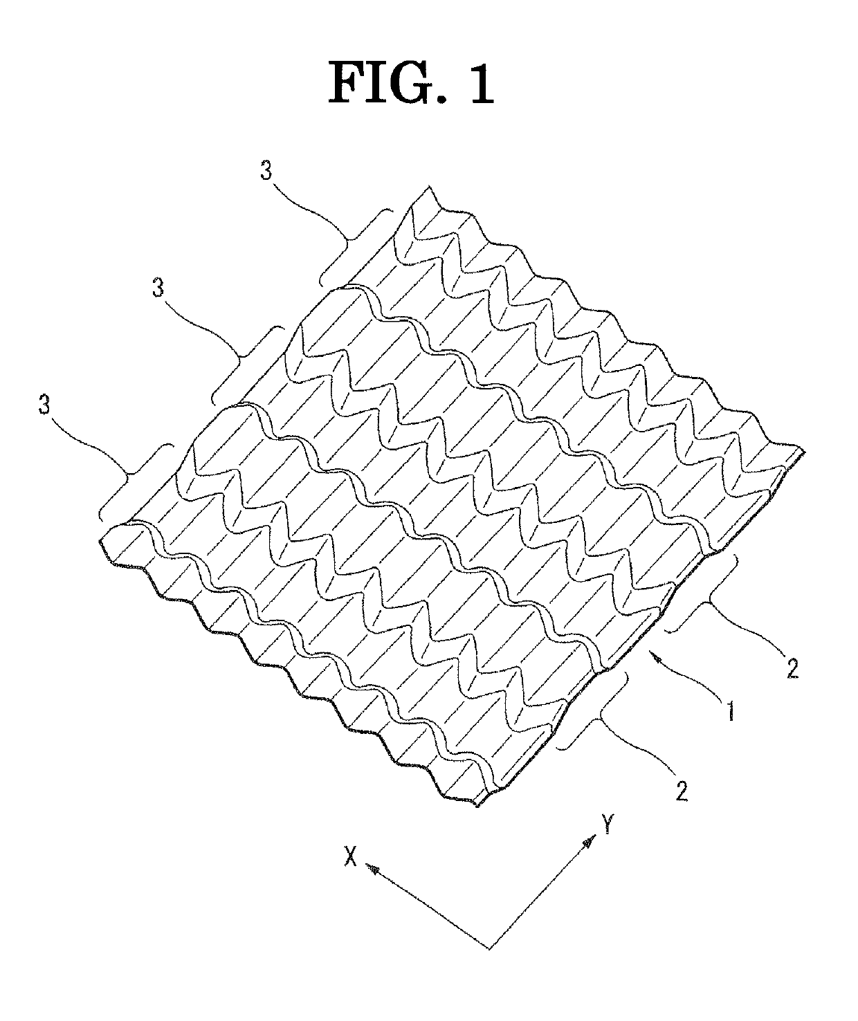
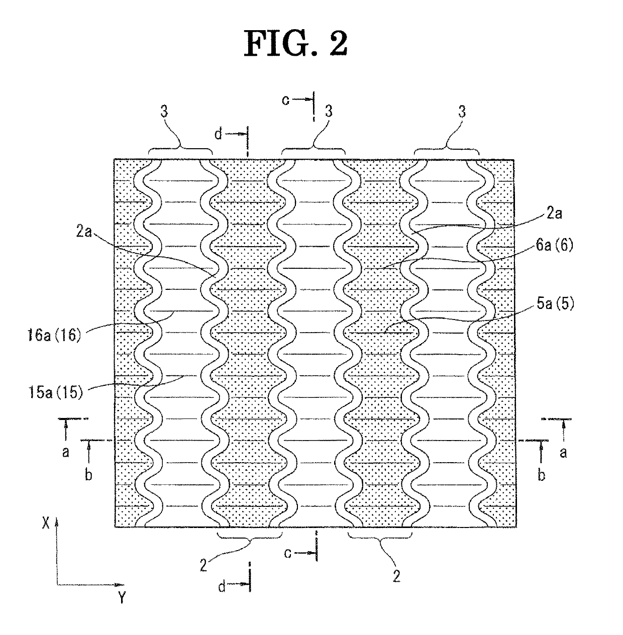
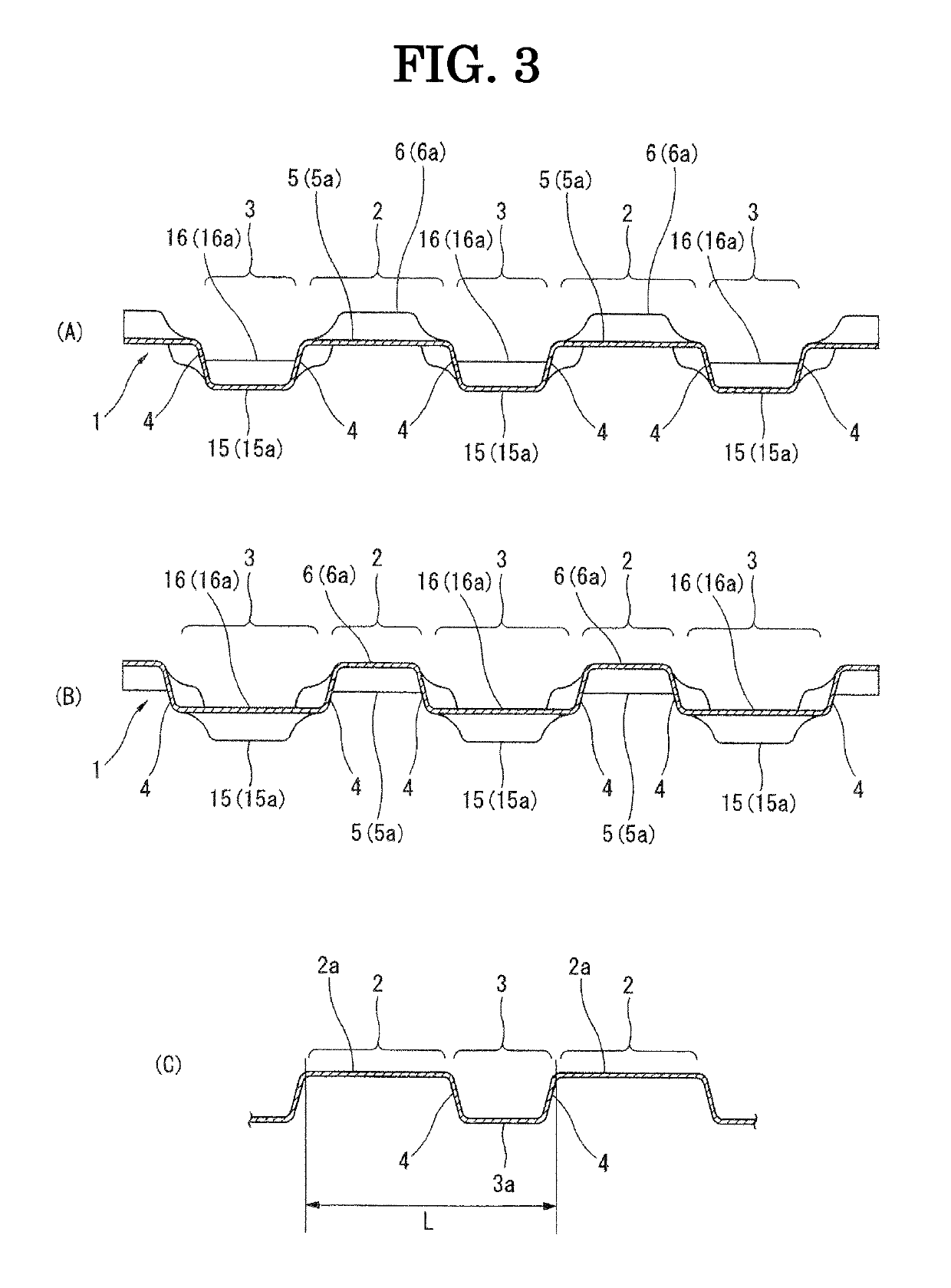
[0034]FIGS. 1-6 show the first embodiment, which is more specific in order to implement the metal plate according to the present invention. In particular, FIG. 1 shows a perspective view from above of a corrugated metal plate, and FIG. 2 is a plan view of FIG. 1. FIGS. 3(A) and 3(B) respectively show sectional views taken along lines a-a and lines b-b of FIG. 2. FIGS. 4(A) and 4(B) respectively show sectional views taken along lines c-c and lines d-d of FIG. 2. Furthermore, for an easy understanding of the corrugated metal plate shown in FIGS. 1 to 4, photographs of the metal plate are shown in FIGS. 13-17.

[0035]In FIG. 2, for an easy understanding of a projection-recess relation between adjacent projection row 2 and recess row 3, only projection row 2 is shown halftone by adding gradation. Furthermore, corrugated metal plate 1 shown in FIG. 1 is formed by using, for example, an aluminum flat plate material having a plate thickness of about 0.6 mm as a base plate. The plate thicknes...

third embodiment

[0067]In this third embodiment, an embossed pattern similar to that of FIG. 2 is a prerequisite. The longitudinal direction of projection row 2 and its adjacent recess row 3 is deviated from X-direction, and the longitudinal axis of projection row 2 and recess row 3 is intentionally in a meandering or bent shape. It is optional to make a meandering shape based on the embossed pattern of FIG. 7. It is preferable to make a meandering shape in a manner to secure rigidity of a three-dimensional product shape and an easy forming.

[0068]This third embodiment also makes it possible to obtain advantageous effects similar to those of the first embodiment.

[0069]FIG. 9 to FIG. 11 show plan views of corrugated metal plate 1 as the fourth to seventh embodiments of a metal plate according to the present invention, and parts common to the first embodiment are designated by the same signs.

[0070]In the fourth embodiment shown in FIG. 9, as is clear from a comparison with FIG. 2, projection row 2 and ...


PUM

PropertyMeasurementUnit
thicknessaaaaaaaaaa
depthaaaaaaaaaa
heightaaaaaaaaaa

Abstract

Projection row (2) and recess row (3) are alternately and successively formed in a direction (Y-direction) perpendicular to a direction (X-direction) of their rows, thereby forming a corrugated cross-sectional shape of a cross-sectional wave shape. Between projection row (2) and recess row (3), there is provided inclined wall surface (4) having a wave shape in plan view. Each of projection row (2) and recess row (3) has a shape in a cross-section along X-direction that is formed into a corrugated cross-sectional shape of a wave shape. Pitch and height difference between valley portion (5) and crest portion (6) in the corrugated cross-sectional shape along this X-direction are smaller, as compared with a relationship between projection row (2) and recess row (3) in the corrugated cross-sectional shape along Y-direction. The corrugated metal plate of such shape has advantages that machining for making cross-sectional shapes in two directions of X and Y into wave shapes is easy and that the flexural rigidity difference between two direction of X and Y is extremely small.

Description

TECHNICAL FIELD[0001]The present invention relates to a so-called corrugated metal plate, in which both of cross-sectional shapes respectively along one particular direction and a direction intersecting the same are formed into a wave shape, and to a metal cover employing the metal plate. For example, it relates to a metal plate, which is suitably used as one that is arranged close to an automobile's heat generating section for the purpose of heat insulation, and to a metal cover employing the metal plate.BACKGROUND ART[0002]A corrugated metal plate is frequently used as a heat insulation cover (also referred to as a heat insulator, including one having a vibration-damping function and / or sound absorption function) that is arranged close to an exhaust manifold or exhaust pipe (muffler) as an automobile's heat generating section. A typical corrugated metal plate is proposed in Patent Publication 1.[0003]The corrugated metal plate disclosed in Patent Publication 1 is one which is prep...

Claims


Application Information

Patent Timeline
Patent Type & Authority Patents(United States)
IPC IPC(8): B21D13/02B21D13/04F01N13/14F01N13/18
CPCF01N13/14B21D13/02B21D13/04F01N13/18F01N13/1811F01N2260/20F01N13/102
Inventor FAN, XUMISAKI, ATSUSHI
Owner NISSAN MOTOR CO LTD
Why Eureka
Try Eureka