Secondary nozzle for jet engine

a turbofan engine and second nozzle technology, applied in the direction of machines/engines, sustainable transportation, climate sustainability, etc., can solve the problems of low inlet pressure to the third stream, inability to exhaust the third stream air into the core, and pressure drop of the third stream air, so as to improve the operation of the engine over a conventional turbofan engine, increase the cooling capacity, and extensive cooling

Active Publication Date: 2019-09-03
GENERAL ELECTRIC CO
View PDF54 Cites 1 Cited by
  • Summary
  • Abstract
  • Description
  • Claims
  • Application Information

AI Technical Summary

Benefits of technology

[0011]By exhausting the third air stream through the secondary exhaust nozzle over the outer flaps, significant improvements in engine operation over a conventional turbofan engine can be realized. The third air duct or FLADE™ duct can provide increased cooling capacity without concerns for air stagnation or backflow due to the low pressure of the air, since this low pressure air, which is still above ambient, can be expelled. The heat exchangers can reliably be depended upon to provide extensive cooling to electrical systems.
[0012]The exhaust of third stream or FLADE™ air allows the core to run at higher temperatures since the reliable supply of cooler third stream cooling air allows for protection of the turbine. Heat exchangers in the third stream can be used to reduce the temperature of the turbine cooling air and allow the turbine hardware to survive in the increased temperature environment.
[0013]Finally, the third duct or FLADE™ duct now can be relied upon not only to exhaust the cooler, low pressure third stream air or FLADE™ duct air continuously, but also to intake the air at the inlet. The third duct or FLADE™ duct now accepts much of the inlet wall distortion and minimizes the inlet distortion on the fan, the core or bypass air. This allows the fan and core / compressor to operate with less stall margin. When the fan and core operate at less stall margins, the engine can operate at higher pressure ratios, which translates into greater thrust and efficiency. Also, the exhausting of air through the nozzle of the third stream duct or FLADE™ duct over the outer flaps additionally reduces boat tail drag while producing a more stable flow field over the outer flaps.

Problems solved by technology

However, placement of heat exchangers within the third air stream in recent embodiments to take advantage of the low temperatures of the air flowing in the third stream duct or FLADE™ duct have resulted in pressure drops of the air in the third stream duct or FLADE™ duct.
The changes in pressure by the introduction of heat exchangers have resulted in the inability to exhaust the third stream air into the core exhaust at conditions in which exhaust pressure is high, such as at high power operation, and the inlet pressure to the third stream is low, such as low Mach points.
The result would be cessation of flow of air, or insufficient flow of air, in the third stream duct under these flight conditions, which could result in stagnation of air flow in the third stream duct and even backflow of gases (reversal of flow).
Stagnation of the third stream flow air can lead to stall conditions on the blade-on-fan arrangement under certain circumstances, resulting in possible hardware damage and additional drag on the aircraft due to fan inlet spill drag.
What is needed is an arrangement in which the third stream duct air can be exhausted continuously so that there is no cessation or significant reduction of air flow in the third stream duct or in the FLADE™ duct at any operational conditions of the engine, as insufficient air flow could adversely affect cooling of heat exchangers or other hardware dependent on third stream air for cooling.

Method used


Image

  • Secondary nozzle for jet engine
  • Secondary nozzle for jet engine
  • Secondary nozzle for jet engine

Examples


Embodiment Construction

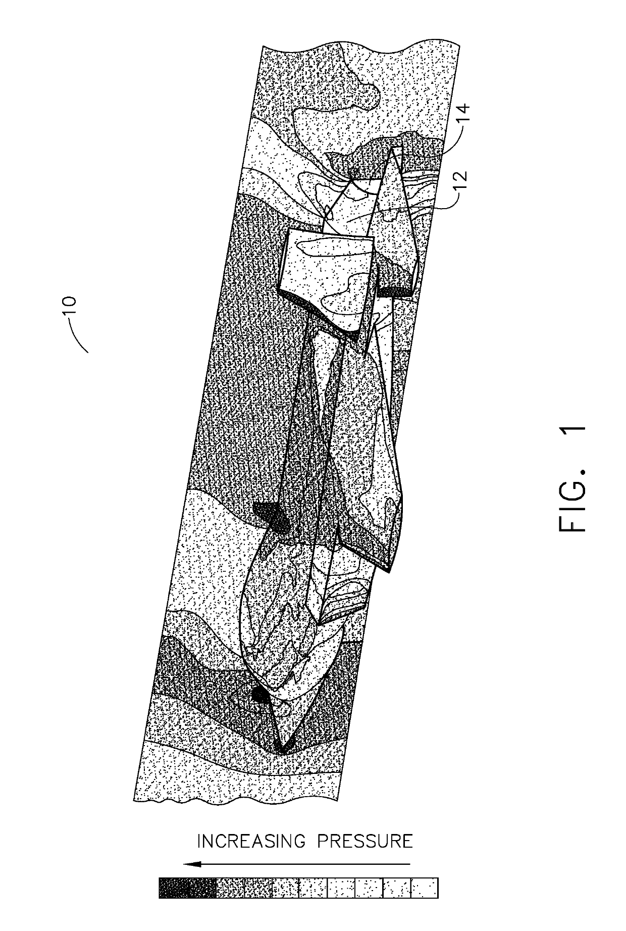
[0022]In modern fighter aircraft, the engine may be installed in an engine bay of the aircraft, and a gap exists between the engine and the aircraft structure. Air flows through this gap and the air flowing though this gap exits or exhausts at the leading edge of the outer flaps where the air pressure is at ambient or sub-ambient conditions. FIG. 1 depicts the pressure contours along the exterior of a jet 10. The low pressure region is shown along outer flaps 12 of engine 14 at a predetermined speed.

[0023]The differences between the turbofan of the present invention having the FLADE™ air stream and a conventional turbofan engine having two airstreams can be appreciated with reference to FIG. 5, which depicts a turbofan that includes a FLADE™ duct or third stream duct and FIG. 4, which depicts a conventional turbofan engine. FLADE™ duct and third stream air duct, as well as FLADE™ air stream and third air stream may be used interchangeably herein, the differences between the two bein...


PUM


Abstract

A third stream duct producing a third air stream at reduced pressure that is exhausted through a separate nozzle that is concentric with the main or primary engine nozzle. The third stream exhaust air from the separate concentric nozzle is exhausted to a location at which pressure is ambient or sub-ambient. The location at which the third stream air is exhausted contributes to the thrust of the aircraft. The airstream from the third air duct is exhausted through an exhaust nozzle of the third duct that is positioned at the interface between the aft of the airframe and the leading edge of the engine outer flaps. This location is a low pressure region that has a recirculation zone. The exhaust of third stream air to this low pressure region substantially reduces or eliminates this recirculation zone and associated boat tail drag, thereby improving the efficiency of the engine.

Description

CROSS-REFERENCE TO RELATED APPLICATIONS[0001]This application is related to application No. 13 / 888,967, which was filed with the U.S. Patent and Trademark Office on even date as the present application and is incorporated herein by reference.FIELD OF THE INVENTION[0002]The present invention is directed to a three stream turbofan engine, and specifically to exhausting third stream flow over a low pressure region.BACKGROUND OF THE INVENTION[0003]Most aircraft engines finding use in military applications, such as air combat, reconnaissance and surveillance, are augmented turbofans. Augmentation provides additional thrust for the aircraft when called upon, that is, on-demand.[0004]All turbofan engines include at least two air streams. All air utilized by the engine initially passes through a fan, and then it is split into the two air streams. The inner air stream is referred to as core air and passes into the compressor portion of the engine, where it is compressed. This air then is fed...

Claims


Application Information

Patent Timeline
Patent Type & Authority Patents(United States)
IPC IPC(8): F02K3/077F02K3/12F02K3/02F02K3/075F02K1/12F02K1/82
CPCF02K1/1292F02K1/822F02K3/075F02K3/025F02K3/077Y02T50/672Y02T50/675Y02T50/60
Inventor DAWSON, DAVID LYNNLARIVIERE, ERIN LEEPETERSEN, BRIAN JOSEPHELLERHORST, ROBERT JEROME
Owner GENERAL ELECTRIC CO
Why Eureka
Try Eureka