
Compact antenna apparatus for mobile communication system

a mobile communication system and compact technology, applied in the direction of antenna details, antenna housings, radiating element housings, etc., can solve the problems of inability to secure elements like a large antenna apparatus, inability to transmit radio waves according to the environment, and space for automatic tilting modules, so as to minimize the error range of tilting angle, improve beam forming accuracy, and accurate adjust the tilting angle

Active Publication Date: 2019-09-03
KMW INC
View PDF15 Cites 1 Cited by
  • Summary
  • Abstract
  • Description
  • Claims
  • Application Information

AI Technical Summary

Benefits of technology

This configuration allows for precise tilting angle adjustments, minimizing errors and costs, while maintaining high radiation performance and improving beam forming accuracy.

Problems solved by technology

Meanwhile, in the mobile communication services using a radio wave, there may be areas to which the radio wave cannot be transmitted according to the environment, such as terrains and buildings, due to characteristics of the radio wave.
That is, in the compact antenna apparatus, a size of a radome provided with the radiating element cannot but be relatively small, and therefore the compact antenna apparatus has a problem in that a space for an automatic tilting module for automatically adjusting a tilting angle of the radiating element like a large antenna apparatus may not be secured.
In addition, the compact antenna apparatuses are greatly affected by buildings and terrains due to the high frequency band and therefore should be installed in a lot of places.
However, there may be the problem that the installation of the automatic tilting module in each compact antenna apparatus requires high additional expenses.
In addition, since the size of the radome is small in the compact antenna apparatus, the number of radiating elements installed in the compact antenna apparatus should be inevitably much smaller than that of the large antenna apparatus.
That is, if the tilting angle of the radiating element is automatically adjusted, the radiating element of the compact antenna apparatus has a problem in that an error range of the tilting angle becomes large.
If the error of the tilting angle becomes large, there may arise a problem in that the frequency band may be changed, radiation performance may be degraded, the radiation performance may not be realized properly, or the like.
Further, if the antenna apparatus is installed on the high outer wall, it is difficult for an operator to manually adjust the tilting angle of the radiating element.

Method used


Image

  • Compact antenna apparatus for mobile communication system
  • Compact antenna apparatus for mobile communication system
  • Compact antenna apparatus for mobile communication system

Examples


Embodiment Construction

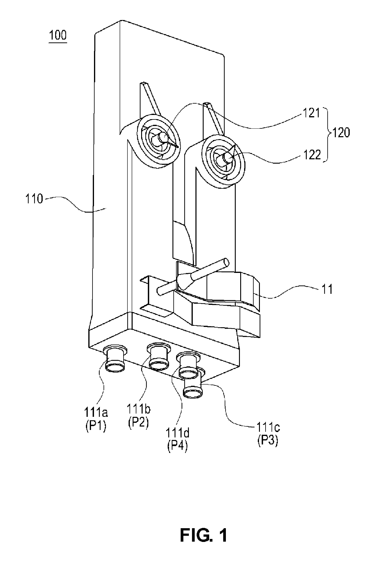
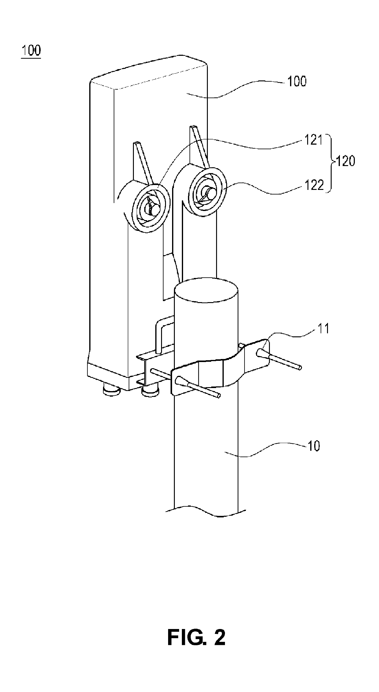
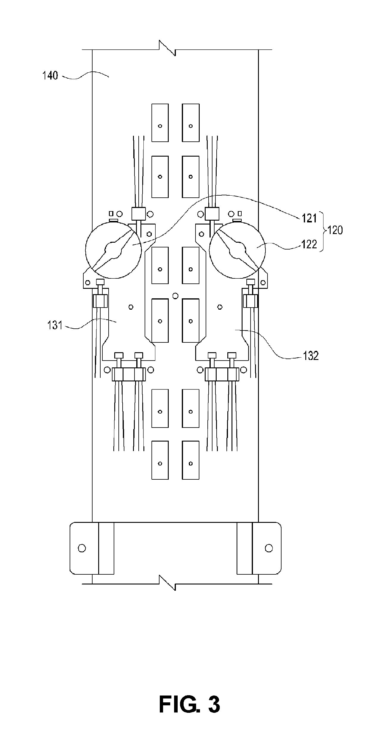
[0020]100: Compact antenna apparatus for mobile communication system

[0021]110: Radome

[0022]120: Rotary knob portion 130: Phase shifter portion

BEST MODE

[0023]The present disclosure may be modified in various ways and implemented by various exemplary embodiments, so that some exemplary embodiments are described in detail with reference to the accompanying drawings. However, it is to be understood that the present disclosure is not limited to the specific exemplary embodiments, but includes all modifications, equivalents, and substitutions included in the spirit and the scope of the present disclosure.

[0024]Terms including an ordinal number such as ‘first’, ‘second’, etc. can be used to describe various components, but the components are not to be construed as being limited to the terms. The terms are only used to differentiate one component from other components. For example, the ‘first’ component may be named the ‘second’ component and the ‘second’ component may also be similarly nam...


PUM


Abstract

A compact antenna apparatus for a mobile communication system includes: a radome having at least one frequency band radiating element provided therein; at least one phase shifter portion which is provided in an inner side of the radome and which is connected to the radiating element to adjust a tilting angle of the radiating element; and a rotary knob portion which is provided so as to be exposed to the outside of the radome and which is directly coupled to the phase shifter portion to drive a phase shifter.

Description

CROSS-REFERENCE TO RELATED APPLICATIONS[0001]This application is a continuation of International Application No. PCT / KR2015 / 013036 filed on Dec. 2, 2015, which claims priority to Korean Application No. 20-2014-0008847 filed on Dec. 2, 2014, the entire contents of which are incorporated herein by reference.TECHNICAL FIELD[0002]The present disclosure relates to a compact antenna apparatus that may be applied to a base station or a relay station in a mobile communications (PCS, cellular, CDMA, GSM, LTE, etc.) network.BACKGROUND ART[0003]Typically, a base station of a mobile communication system has been divided into a base station main body apparatus for processing a transmitting and receiving signal and an antenna apparatus including a plurality of radiating elements to transmit and receive radio signals. Generally, the base station main body apparatus is installed at a low-lying land on the ground and the antenna apparatus is installed at high positions such as a building roof and a ...

Claims


Application Information

Patent Timeline
Patent Type & Authority Patents(United States)
IPC IPC(8): H01Q3/32H01Q3/08H01Q1/42H01Q3/26H01P1/18H01Q21/10H01Q3/22H01Q3/02H01Q1/24H01Q1/12
CPCH01P1/18H01Q1/246H01Q3/08H01Q3/22H01P1/184H01Q21/10H01Q1/42H01Q3/02H01Q3/26H01Q3/32H01Q1/1228H01Q1/247H01Q3/2605
Inventor MOON, YOUNG-CHANKIM, IN-HOCHOI, OH-SEOGYANG, HYOUNG-SEOKKIM, SANG-HYEONGKIM, HEEJUNG, HYE-MI
Owner KMW INC
Learn More