Light emitting apparatus
a technology light emitting diodes, which is applied in the direction of light emitting and heating apparatus, semiconductor devices for light sources, transportation and packaging, etc., can solve the problems of long life span of light emitting diodes and laser diodes, low power consumption, and inevitably occurring aberrations, so as to improve the quality of spots, reduce the cost of production, and improve the design freedom of light emitting apparatus
Active Publication Date: 2019-09-10
LG INNOTEK CO LTD
View PDF25 Cites 0 Cited by
- Summary
- Abstract
- Description
- Claims
- Application Information
AI Technical Summary
Benefits of technology
The solution enhances the reliability and efficiency of the light emitting apparatus by maximizing reflectance to 100%, reducing the risk of damage from concentrated light beams, and improving the quality of the spot formed on the wavelength conversion unit, while minimizing the impact of working distance on focus size, thus offering increased design freedom and cost-effectiveness.
Problems solved by technology
In addition, the light emitting diodes and the laser diodes exhibit long life spans and low power consumption.
If the size of the single focusing lens is increased, aberration may inevitably occur.
That is, in the conventional optical apparatus using the light sources, a complicated optical system, including collimating lenses, a prism, and a focusing lens, is required, whereby the structure of the optical apparatus may be complicated and the quality of a spot formed on a single point may be deteriorated.
Method used
View moreImage
Smart ImageViewing Examples
Examples
Embodiment Construction
[0113]Various embodiments have been described in the best mode for carrying out the invention.
INDUSTRIAL APPLICABILITY
[0114]A light emitting apparatus according to embodiments may be used in various lamps for vehicles (e.g. a low beam, a high beam, a taillight, a side light, a signal light, a day running light (DRL), and a fog light), a flashlight, a traffic light, or various lighting devices.
Login to View More PUM
 Abstract
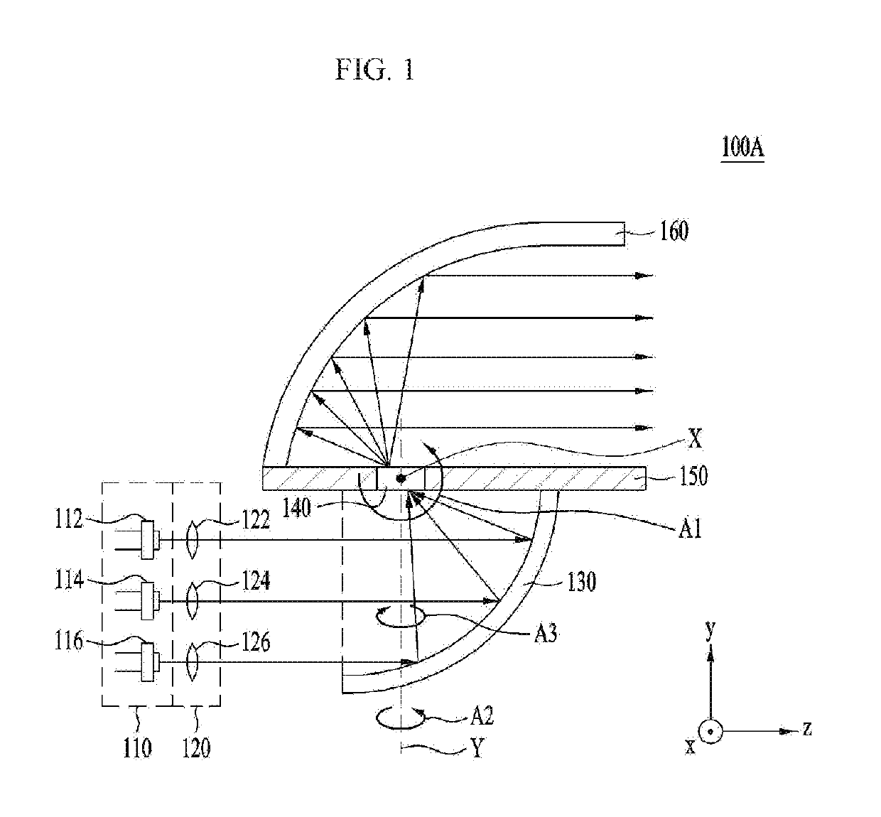
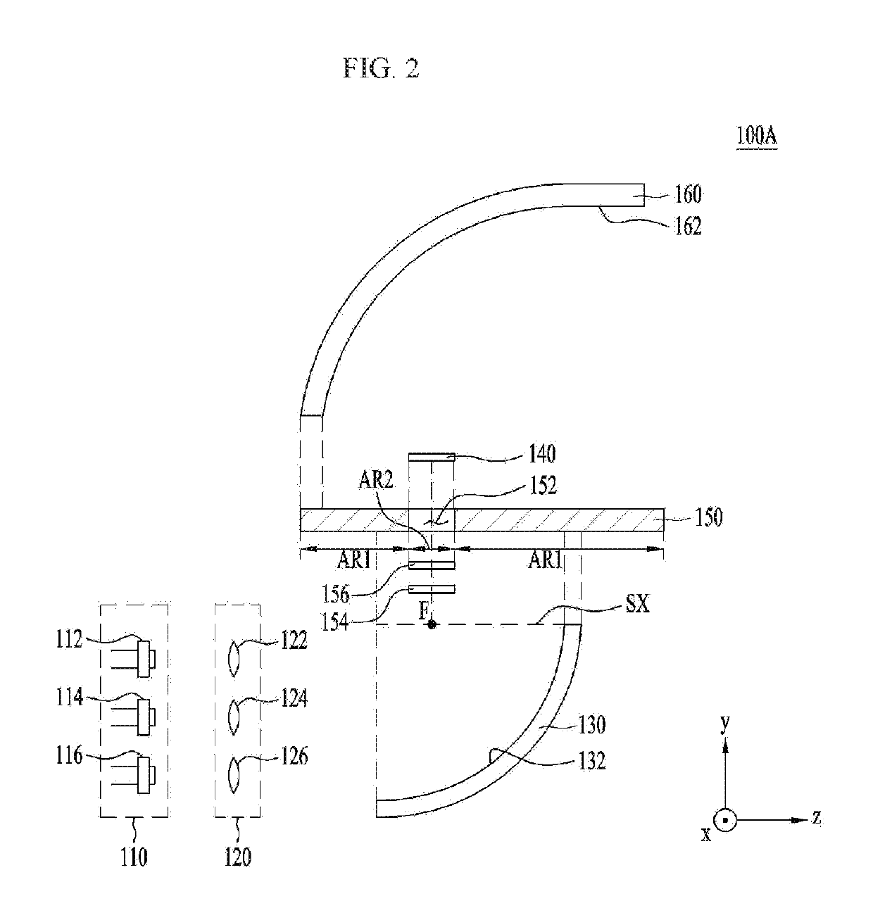
A light emitting device apparatus of an embodiment comprises: a light source unit for emitting a plurality of excitation lights having linearity; a first reflection unit which reflects the plurality of excitation lights having linearity and incident to an incident direction parallel to an axis of symmetry, and collects the plurality of excitation lights to a focus position; and a wavelength conversion unit which is arranged on the focus position and transmits the plurality of excitation lights reflected and collected by the first reflection unit.
Description
CROSS-REFERENCE TO RELATED APPLICATIONS[0001]This application is the U.S. national stage application of International Patent Application No. PCT / KR2015 / 013993, filed Dec. 21, 2015, which claims priority to Korean Patent Application No. 10-2015-0017029, filed Feb. 3, 2015, the disclosures of each of which are incorporated herein by reference in their entirety.TECHNICAL FIELD[0002]Embodiments relate to a light emitting apparatus.BACKGROUND ART[0003]Light emitting diodes (LEDs) are a kind of semiconductor device that sends and receives a signal by converting electricity into infrared light using the characteristics of compound semiconductors or that is used as a light source.[0004]A group III-V nitride semiconductor has been in the spotlight as the core of light emitting devices, such as light emitting diodes (LEDs) or laser diodes (LDs), due to the physical and chemical characteristics thereof.[0005]Light emitting diodes and laser diodes do not contain environmentally hazardous substa...
Claims
Login to View More Application Information
Patent Timeline
 Patent Type & Authority Patents(United States)
IPC IPC(8): F21K9/64F21S41/16F21S41/19F21S41/20F21S41/32F21S45/47F21S45/49F21V13/04H01L33/50H01L33/58F21S41/143F21S41/151F21S41/365F21V7/00F21V7/06F21V9/30F21Y115/00F21Y115/10F21Y115/30
CPCF21V7/0033F21S41/151F21S41/16F21S41/19F21S41/285F21S41/321F21S41/365F21S45/47F21S45/49F21V7/06F21V9/30F21V13/04H01L33/50H01L33/58F21S41/143F21Y2115/30F21K9/64F21Y2115/00F21Y2115/10F21V13/14F21S41/176F21V9/32F21V9/40
Inventor PARK, KANG YEOLKIM, KI CHEOLSON, CHANG GYUN
Owner LG INNOTEK CO LTD
Features
- R&D
- Intellectual Property
- Life Sciences
- Materials
- Tech Scout
- Unparalleled Data Quality
- Higher Quality Content
- 60% Fewer Hallucinations
Learn More Browse by: Latest US Patents, China's latest patents, Technical Efficacy Thesaurus, Application Domain, Technology Topic, Popular Technical Reports.
© 2025 PatSnap. All rights reserved.Legal|Privacy policy|Modern Slavery Act Transparency Statement|Sitemap|About US| Contact US: help@patsnap.com


