
Duct structure

a technology of duct structure and duct head, which is applied in the direction of charging feed system, lighting and heating apparatus, combustion engines, etc., to achieve the effect of suppressing the flow separation from the inner surface of the duct at the downstream of the fin, and reducing the pressure drop at the fin

Active Publication Date: 2019-09-17
TOYOTA JIDOSHA KK
View PDF15 Cites 3 Cited by
  • Summary
  • Abstract
  • Description
  • Claims
  • Application Information

AI Technical Summary

Benefits of technology

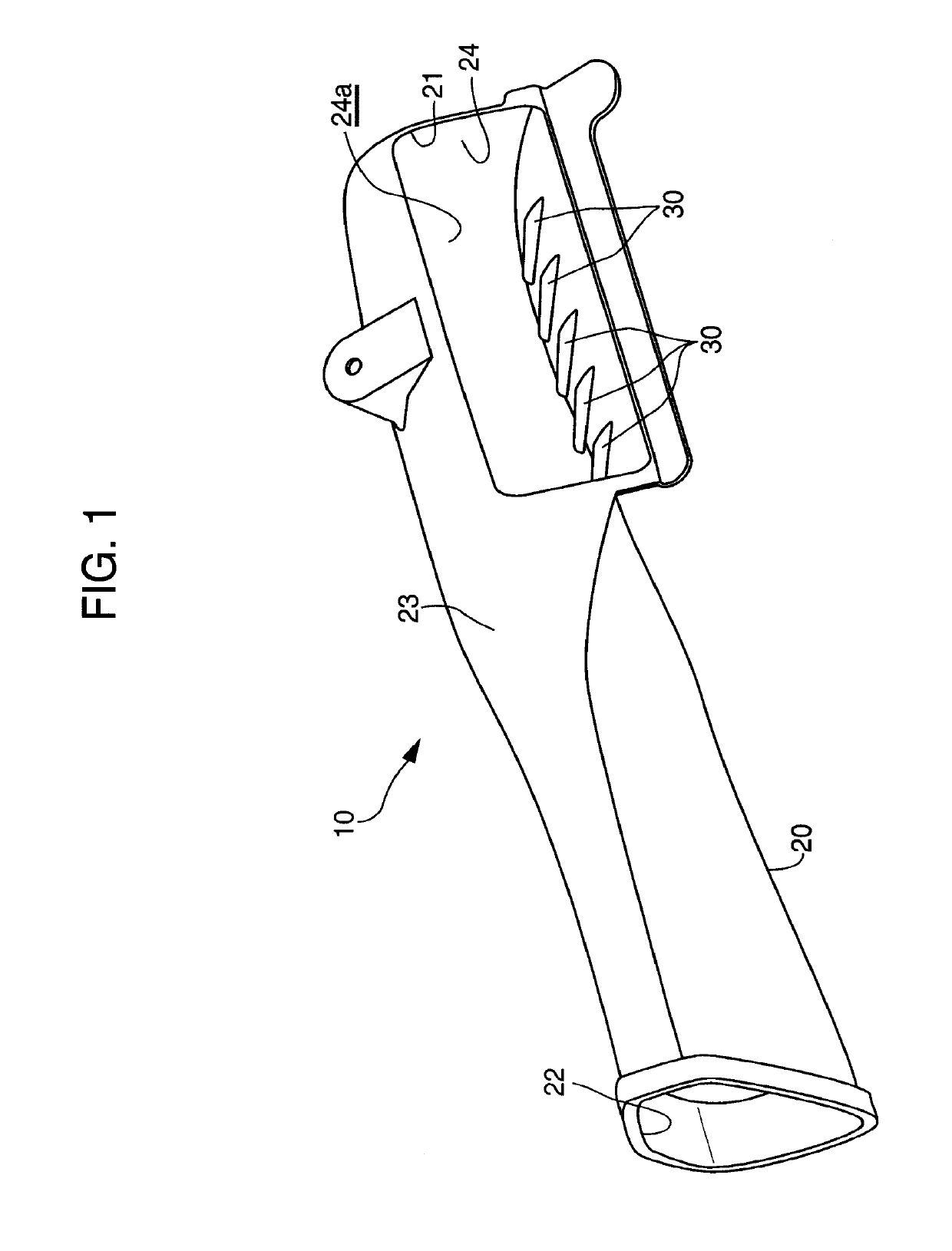
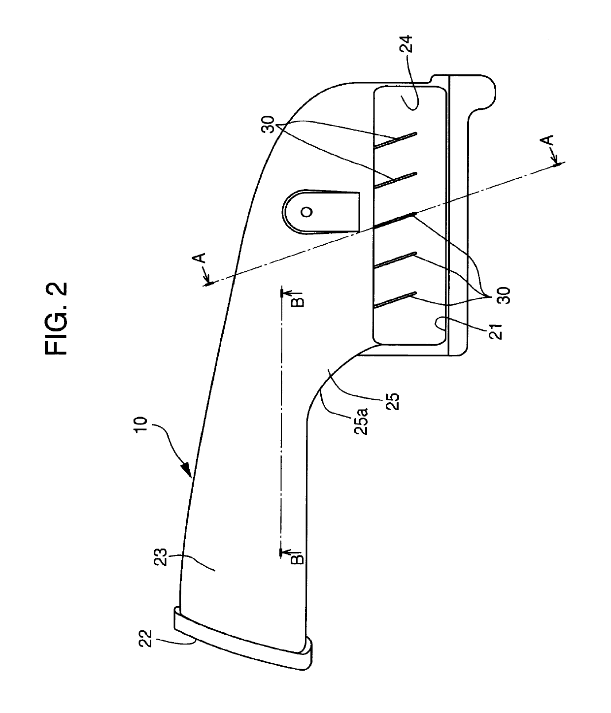
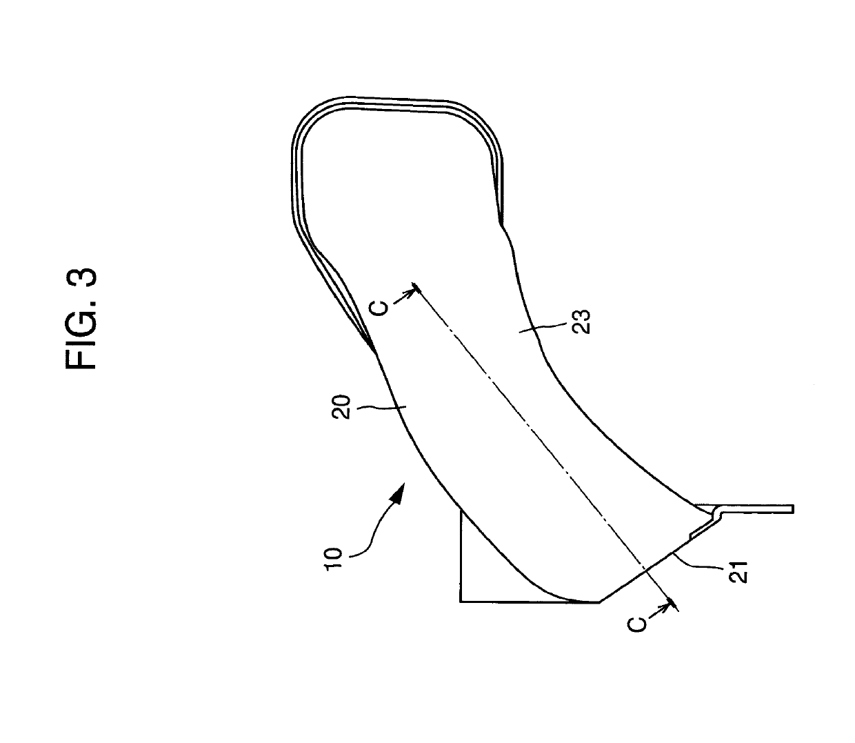
The duct structure described in this patent text has several technical effects. First, the fin is inclined to direct the flow of fluid towards the inner side of curved portions in the duct, reducing flow separation and pressure drop. Second, the fin includes an inclined surface that allows a flow to flow along it, reducing flow resistance and pressure drop. Third, the duct structure includes a space with a larger cross-sectional area than the duct, preventing flow separation from the inner surface at the curved portion or downstream of the fin. Fourth, the fin is located close to the inlet, suppressing flow separation at the curved portion or downstream of the fin. Fifth, the fin is formed integrally with the duct, reducing the number of parts and manufacturing steps. Finally, the duct structure can improve engine output and reduce cross-sectional area of the fluid passage.

Problems solved by technology

However, there are the following problems with the structure disclosed in Patent Document 1 above:

Method used


Image

  • Duct structure
  • Duct structure
  • Duct structure

Examples


embodiment 1

[0080]Structures of portions unique to Embodiment 1 will be explained.

[0081]In Embodiment 1, the fin 30 includes a top surface 32 shown in FIG. 9 and a pair of side surfaces 33 having side surface portions 33b parallel with each other shown in FIG. 10.

[0082]As illustrated in FIG. 9, the top surface 32 of the fin includes an upstream end and a downstream end. The upstream end and the downstream end of the top surface 32 may coincide with the upstream end 30a and the downstream end 30b, respectively, of the fin in position in the longitudinal direction of the fin. The top surface 32 of the fin extends from the upstream end 30a of the top surface 32 to the downstream end 32c of the top surface 32 of the fin in the longitudinal direction of the fin. The downstream end 32c of the top surface 32 of the fin is spaced away from the inner surface 24 of the duct 20.

[0083]A cross-sectional configuration of the top surface 32 of the fin taken along a flat plane perpendicular to the longitudinal...

embodiment 2

[0098]Next, structures of portions unique to Embodiment 2 will be explained.

[0099]In Embodiment 2, as illustrated in FIGS. 16 and 17 the thickness of the fin 30 is gradually decreased in a direction away from a root of the fin in the height direction of the fin.

[0100]As illustrated in FIGS. 16 and 17, the fin 30 may include an angled ridge (hereinafter, a ridge) 36 at a higher end of the fin in the height direction of the fin. Contrarily, as illustrated in FIGS. 18 and 19, the ridge at the higher end of the fin may be replaced by a curved surface or a flat plane. In the explanation about Embodiment 2 below, the fin 30 having the ridge 36 will be taken as an example of the fin.

[0101]As illustrated in FIG. 14, the ridge 36 of the fin includes an upstream end and a downstream end 36c. The upstream end and the downstream end of the ridge 36 of the fin may coincide with the upstream end 30a and the downstream end 30b, respectively, of the fin in position in the longitudinal direction of ...


PUM


Abstract

A duct structure including a fin having a downstream end surface extending between an inner surface of a duct and a downstream end of a top surface of the fin in a height direction of the fin. As a result, a vortex can be intentionally generated in a downstream of the downstream end surface of the fin. Since a pressure in the vortex is lower than a pressure in a surrounding portion of the vortex, the vortex can draw a fluid flow having flowed along the top surface of the fin to the vortex and can change the flow to a flow flowing along a portion of the inner surface of the duct located downstream of the fin. As a result, a flow separation from the inner surface of the duct can be suppressed.

Description

TECHNICAL FIELD[0001]The present application relates to a duct structure having a flow control fin.BACKGROUND[0002]At an inlet of a duct and a curved portion of the duct, a flow is disturbed and a flow separation from an inner surface of the duct is likely to occur.[0003]In order to suppress occurrence of a flow separation from an inner surface of the duct, as illustrated in FIG. 20, Patent Document 1 discloses a structure where a flow control plate 3 formed in a form of a lattice is provided at a portion of a duct 2 close to an inlet 2a. The flow control plate 3 is provided so as to extend over an entire cross-section of the inlet 2a of the duct in a width direction and a height direction of the duct.[0004]However, there are the following problems with the structure disclosed in Patent Document 1 above:[0005]Since the flow control plate 3 is provided so as to extend over the entire cross section of the inlet 2a of the duct, a pressure drop caused by the flow control plate 3 is cons...

Claims


Application Information

Patent Timeline
Patent Type & Authority Patents(United States)
IPC IPC(8): F24H9/12F02M35/10
CPCF02M35/10118F02M35/10262Y02T10/146Y02T10/12
Inventor RIKITAKE, SHUNSUKEKONDO, KEISUKE
Owner TOYOTA JIDOSHA KK
Learn More