System and method for targeted data communication

a data communication and target technology, applied in the field of data communication, can solve the problems of limiting the bandwidth available to each connected end node, data transmit rate is limited by requirements, and data transmission devices primarily used for illumination lighting are generally slower than data transmission devices, so as to improve data communication and improve the resource management of data communication

Active Publication Date: 2019-09-17
SIGNIFY HLDG BV
View PDF6 Cites 0 Cited by
  • Summary
  • Abstract
  • Description
  • Claims
  • Application Information

AI Technical Summary

Benefits of technology

[0007]It is an object of the present invention to provide a method and system that improve data communication within an optical communication system, in particular the present invention is dedicated to improve the resource management for data communication in application control networks.
[0014]By determining a position of a communication unit, which may receive and / or transmit data from / to the application control network underlying the application control system, it is possible to select a subgroup of one or more specific application control components capable of data communication which are located in the vicinity of the communication unit for data transmission. In particular, when data is to be transmitted from the application control system to the communication unit, knowledge about the location of the communication unit enables distinct selection of one or more data emitters among the application control components in the vicinity of the receiving communication unit. The remaining application control components may be disregarded for the data emission to that particular communication unit such that their capacity can be used for other data communication or application tasks. The data transmission capacity of an application control component may be limited, especially if the primary task of the application control component is to serve the application control system, e.g. lights used in a lighting control system whose primary purpose is to provide illumination light and which additionally may be used for data transmission. Hence, by observing the position of a receiving communication unit, dynamically determining its location within the network to distinctly inject the data for said receiving communication unit by selecting at least one suitable emitter and automatically programming the data paths to said emitter provides an efficient resource management and effective usage of the available bandwidth. This becomes especially important for dense networks and / or a plurality of communication units or otherwise increased data transmission volumes. The determination of the position of the communication unit may be based on information provided by external sensors that detect the position or may be based on absolute or relative position information provided by the communication unit itself.
[0016]By determining the most likely trajectory of a communication unit within a network to predict its current and next position, the effective selection of suitable emitters / receivers to transmit / receive data to / from said moving communication unit can be enhanced. Furthermore, handover between emitters along the trajectory may be smoothly prepared to ensure proper data delivery.
[0018]Within an application control system there may be application control components whose primary purpose is to fulfil their functionality within the application control system; for example, within a lighting control system the main purpose of a light may be to provide illumination light. However, in addition the light may be used for data transmission. Usually, the capacity for data transmission of light sources primarily dedicated to illumination purposes is rather limited and thus such a light is usually considered a slow emitter. There may be other application control components providing higher data rates for data communication, e.g. emitters which are not used for illumination lighting but that allow to change light levels for data communication, such as colour, on, off, dimming etc. These application control components enable faster data communication. Thus by selecting fast over slow emitters the overall data communication may be improved.
[0029]By combining present and future position information of two or more stationary or moving communication units, the available resources for data transmissions to and from the two or more devices may be distributed in the most effective manner. In one scenario it may be most efficient to share one and the same resource, e.g. application control unit, and multiplex the data transmissions to be send to both receiving units simultaneously. This scenario may be most efficient for the transfer of respective small sized or timely uncritical data transmissions, especially when other resources may be set or remain in a power saving mode. In other cases it may be more efficient to select interleaving, mutually exclusive application control components to serve different communication units. For instance in chase two mobile units are carried along the same path through a building and constantly receive data transmissions from an application control network, it may be advantageous to select mutually interleaving emitters for data transmissions to the respective communication units.

Problems solved by technology

However, a dense distribution of RF transceivers will occupy bandwidth in the spectrum, effectively limiting bandwidth available to each connected end node.
Since a VLC system's main objective is high quality illumination lighting, the data transmit rates are limited by requirements imposed by their primary function.
Light sources primarily used for illumination lighting are therefore generally slower data transmission devices.
In state of the art optical communication systems, it is a challenge to properly deliver data to the receiving end node, especially when the end node is mobile and in transit (i.e. a person carrying a mobile receiver device).
The main problem with such systems is that when the system does not know where the mobile receiver device is located at present, it may inject its data using all emitters, in the hope that the receiver device will pick it up.
Such an approach limits the effective bandwidth within the network and does not scale well with a larger number of mobile end-nodes serviced within the same optical communication system.

Method used


Image

  • System and method for targeted data communication
  • System and method for targeted data communication
  • System and method for targeted data communication

Examples


Embodiment Construction

[0063]Some embodiments are exemplary described in the context of lighting control applications as preferred embodiments. However, it is to be understood that the embodiments are not restricted to lighting control applications. The person skilled in the art will appreciate that the methods and devices may be exploited for any other control application requiring a similar system topology.

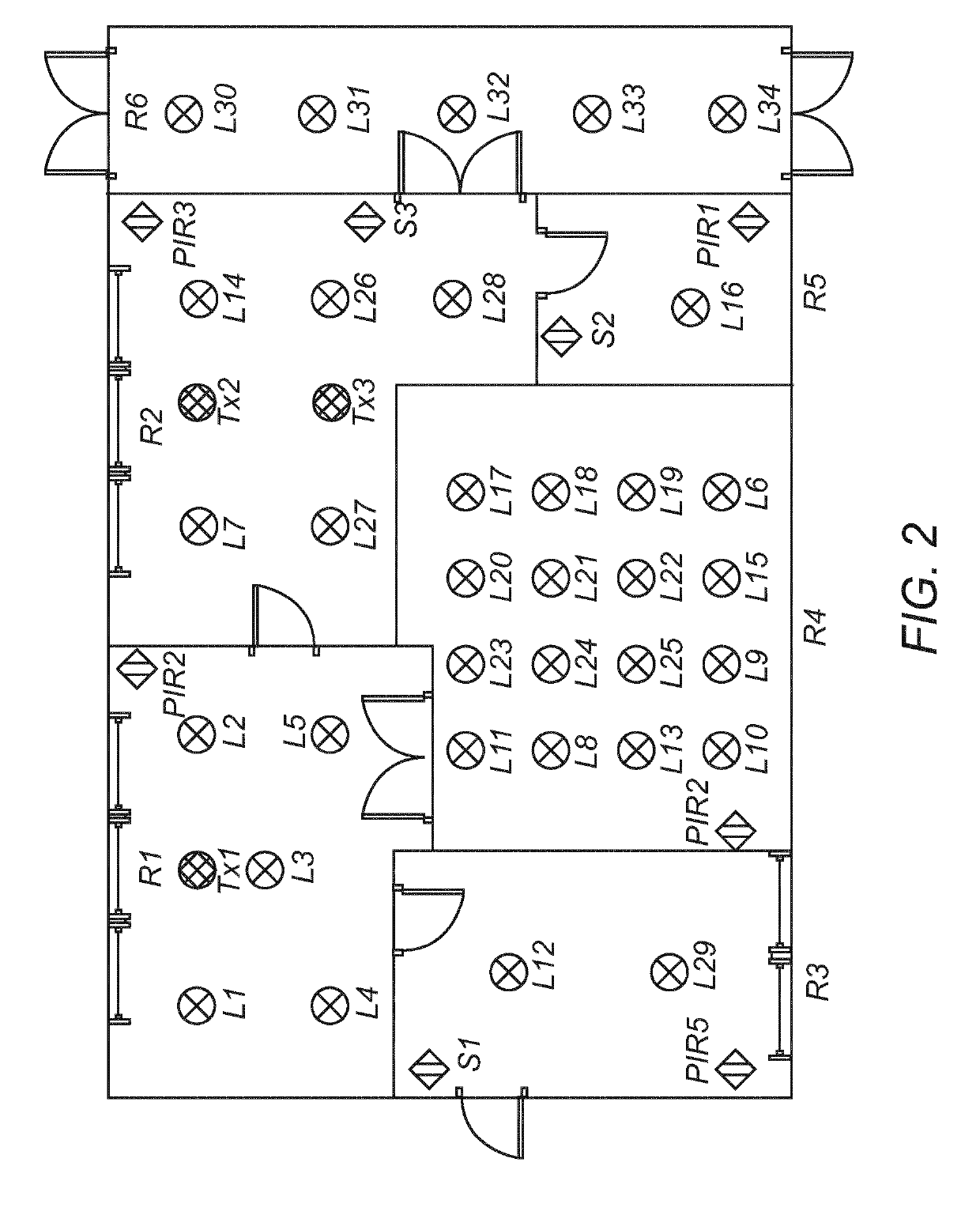
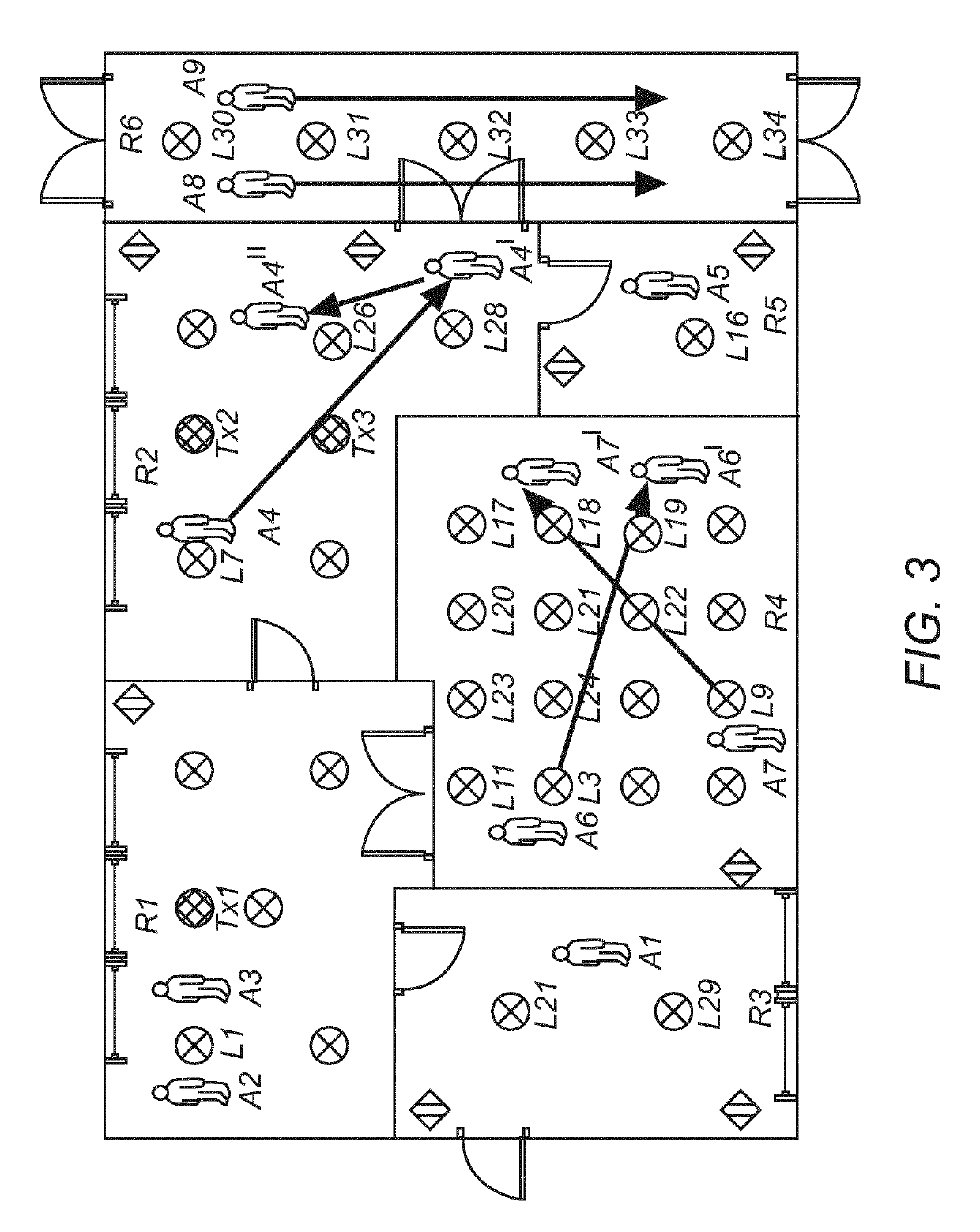
[0064]In the following a software defined application (SDA) system provides knowledge about application specific requirements and instructions as stipulated in an application plan comprising one or more application scenes. For instance, an example of an SDA system is a software defined lighting (SDL) system that defines a lighting plan comprising one or more lighting scenes. A lighting scene may for example define dependencies or interactions between application control components, e.g. which lamps are to be switched on if a particular sensor is triggered. The lighting scenes may be defined for specif...


PUM


Abstract

The invention relates to a method for directing communication traffic to and from a communication unit within an application control system, wherein the application control system comprises a plurality of application control components and the application control components are capable of transmitting messages to the communication unit using light waves. By determining position information of the application control components within the application control system and of a first communication unit within the application control system, an area of interest for the first communication unit is computed based on at least the first position information. A first subgroup of one or more application control components from the plurality of application control components located within the area of interest of the first communication unit is identified and data paths through the application control system are programmed to communicate with the communication unit using the identified subgroup of application control components.

Description

CROSS-REFERENCE TO PRIOR APPLICATIONS[0001]This application is the U.S. National Phase application under 35 U.S.C. § 371 of International Application No. PCT / EP2016 / 077868, filed on Nov. 16, 2016, which claims the benefit of European Patent Application No. 15196399.8, filed on Nov. 26, 2015. These applications are hereby incorporated by reference herein.FIELD OF THE INVENTION[0002]The present invention relates to the field of data communication within an application control system, in particular—but not limited to—Visible Light Communication in lighting control applications. More particular the invention relates to managing and directing communication traffic within an application control system, e.g. targeting data transmissions, embedded in light waves, to selected light emitters.BACKGROUND OF THE INVENTION[0003]In wired communication systems, like for example wired Ethernet, data is provided to an end node via the data path given by a cable connecting the end node's network inter...

Claims


Application Information

Patent Timeline
Patent Type & Authority Patents(United States)
IPC IPC(8): H04B10/114H04B10/116H04W40/20H04W28/26
CPCH04W28/26H04B10/116H04W40/20H04B10/1149
Inventor KAAG, BJORN CHRISTIAAN WOUTERJOHNSON, MARK THOMASDE BRUIJN, FREDERIK JAN
Owner SIGNIFY HLDG BV
Why Eureka
Try Eureka