Electric truck

a technology for electric trucks and trucks, applied in the field of electric trucks, can solve the problems of unfavorable battery position selection, unfavorable battery maintenance, and available battery capacity, and achieve the effect of optimizing energy consumption and improving the range of electric trucks

Active Publication Date: 2019-09-24
KONIG METALL +1
View PDF13 Cites 19 Cited by
  • Summary
  • Abstract
  • Description
  • Claims
  • Application Information

AI Technical Summary

Benefits of technology

[0008]Starting from this prior art, the task underlying the invention is to provide a refrigerated vehicle that is as lightweight as possible, with an optimized utilization of space for the all-electric operation, especially in the inner-city region.

Problems solved by technology

The need for such all-electric-powered small trucks in the range between 3.5 and 7.5 metric tons will grow considerably in the coming years, because many inner cities are exposed, not only due to the fine-dust pollution, nitrogen oxides pollution, especially due to diesel vehicles, but also due to the resulting noise pollution, to considerable impairments and health hazards, and so now even temporary bans on travel are being considered.
The results achieved heretofore in this connection are unsatisfactory, because the vehicles are usually too heavy for a permanent electrical operation, the battery capacities available in this connection are too small and, in other respects, especially in the food sector, a considerable additional energy demand for maintenance of the refrigeration exists, but can be met only with difficulty by electric vehicles.
In view of the limited space requirement available in this connection, the battery position selected in this respect is unfavorable.
Moreover, the batteries used for powering electric trucks must be equipped with additional safety features, such as crash protection, for example, which in turn requires additional structural measures and in other respects leads to an increased vehicle weight, which in turn must be paid for with an increased energy demand.

Method used


Image

  • Electric truck
  • Electric truck
  • Electric truck

Examples


Embodiment Construction

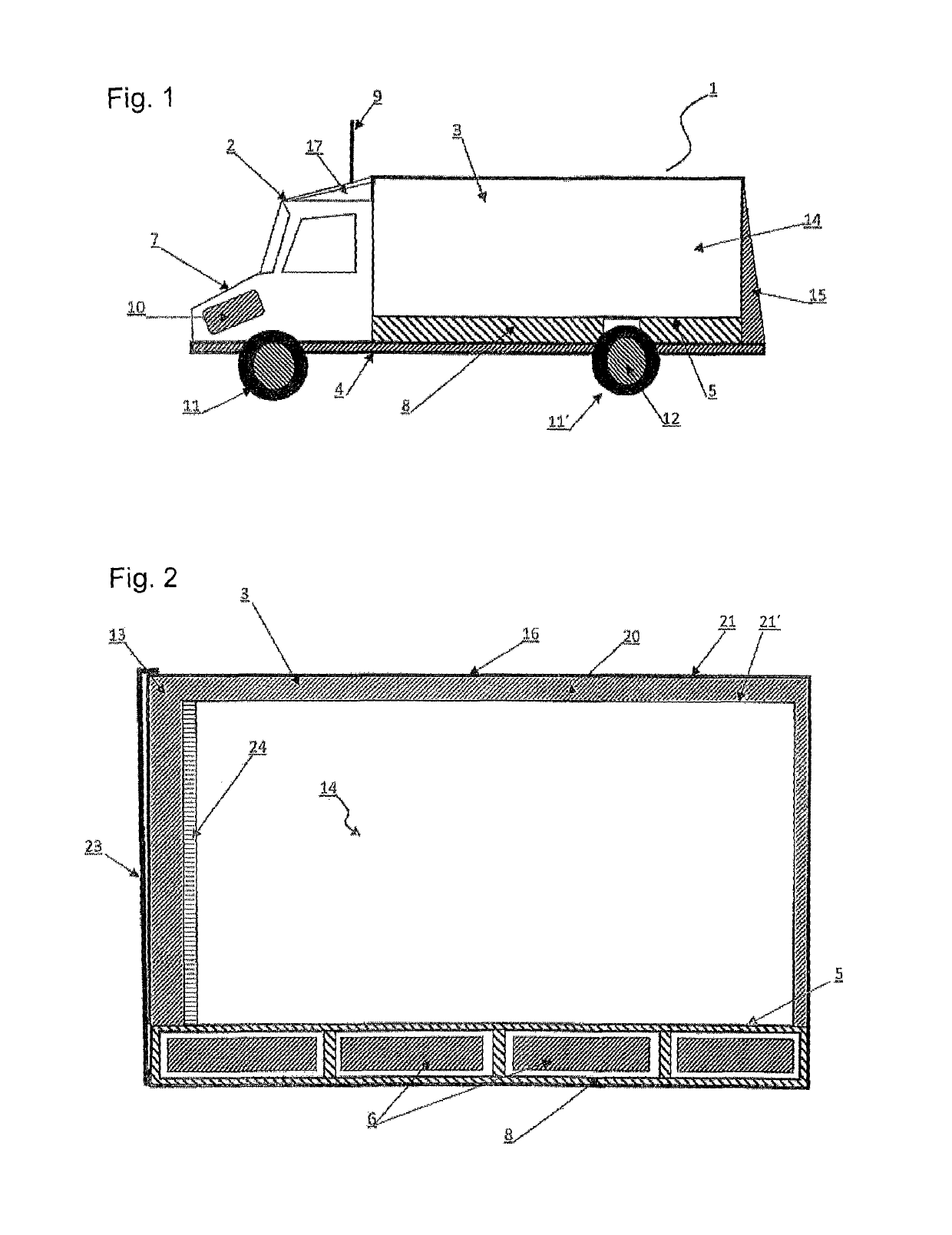
[0041]FIG. 1 shows an electric truck 1 with a driver's cab 2 and a cargo body 3, which respectively rest on the vehicle longitudinal beams 4 disposed on both sides of the electric truck 1, wherein a battery housing 8 with several withdrawable units for in total three batteries 6, 6′, 6″ in this exemplary embodiment is disposed underneath the body bottom 5 extending under the cargo body 3. Properly understood, the body bottom 5 is simultaneously the surface of the battery housing. Cargo body 3 and battery housing 8 therefore represent a closed unit.

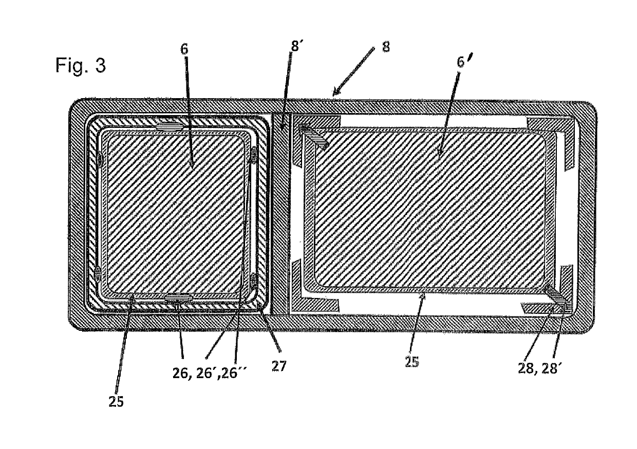
[0042]In this connection, a regulated electric motor 10 is disposed in the motor compartment 7 disposed in front of and underneath the driver's cab 2. Alternatively, wheel-hub motors 12 respectively powered directly by the batteries 6, 6′, 6″ disposed in the battery housing 8 may also be associated with the wheels 11, 11′ of the electric truck 1. The cargo body 3 is bounded by a front wall 13 (FIG. 2) facing the driver's cab 2, two side wa...


PUM

PropertyMeasurementUnit
voltageaaaaaaaaaa
volumeaaaaaaaaaa
weightaaaaaaaaaa

Abstract

An electric truck has a chassis, on which a driver's cab with a motor compartment containing an electric motor is disposed in the front of the electric truck, and in the rear a cargo body rests on the chassis. The cargo body substructure sits on vehicle longitudinal beams of the chassis. The cargo body bottom sealing the cargo body on the underside is spaced above the vehicle longitudinal beams to ensure clearance for a sufficient spring travel. A battery housing with at least one integrated battery is disposed in the intermediate space between the vehicle longitudinal beams and the body bottom, so that a larger installation space is available for the batteries and therefore a greater range for the electric truck. The battery is protected in this region and, moreover, the insulation of the battery housing simultaneously contributes to insulation of the cargo body disposed above the battery housing.

Description

CROSS REFERENCE TO RELATED APPLICATIONS[0001]Applicants claim priority under 35 U.S.C. § 119 of German Application No. 10 2016 116 017.2 filed Aug. 29, 2016 and German Application No. 10 2017 102 064.0 filed Feb. 2, 2017, the disclosures of which are incorporated by reference.BACKGROUND OF THE INVENTION[0002]1. Field of the Invention[0003]The invention relates to an electric truck with a chassis, on which a driver's cab with a motor compartment containing an electric motor is disposed in the front region of the electric truck, and in the rear region a cargo body rests on the chassis of the electric truck, wherein the substructure of the cargo body is seated on the vehicle longitudinal beams of the chassis and wherein the body bottom of the cargo body sealing the cargo body on the underside is disposed with spacing above the vehicle longitudinal beams to ensure clearance for a sufficient spring travel.[0004]2. Description of the Related Art[0005]Such electric trucks are known in part...

Claims


Application Information

Patent Timeline
Patent Type & Authority Patents(United States)
IPC IPC(8): B60K1/04H01M2/10H01M10/46B60L1/02B60L3/00B60L50/60B60L50/64B60H1/00B62D33/04G07C5/00B60P3/20H02S40/38B60K1/00B60K7/00
CPCH01M2/1077H01M2/1083B60P3/20B60H1/00364B60L50/64B62D33/048B60L50/66B60L1/02G07C5/008B60L3/0015B60H1/00014B60K1/04H01M10/465B60H1/00535B60H1/005B60K1/00H02S40/38B60K2001/0416B60Y2200/141B60K2001/0438B60Y2200/14H01M2220/20B60K7/0007B60K2001/001B60K2001/0461Y02E10/50Y02T10/70Y02E60/10Y02E70/30H01M50/229H01M50/204H01M50/249H01M50/242H01M50/289
Inventor KERSPE, JOBST H.FISCHER, MICHAELERHARDT, JUERGEN
Owner KONIG METALL
Why Eureka
Try Eureka