
Electric brake device

a technology of brake device and electric motor, which is applied in the direction of brake system, mechanical apparatus, transportation and packaging, etc., can solve the problems of increasing the calculation load or overflow of variables, difficult design of control system, and increasing the calculation load. , to achieve the effect of easy design

Active Publication Date: 2019-10-01
NTN CORP
View PDF29 Cites 0 Cited by
  • Summary
  • Abstract
  • Description
  • Claims
  • Application Information

AI Technical Summary

Benefits of technology

[0012]An object of the present invention is to provide an electric brake device that allows a control system to be easily designed without making brake feeling worse.
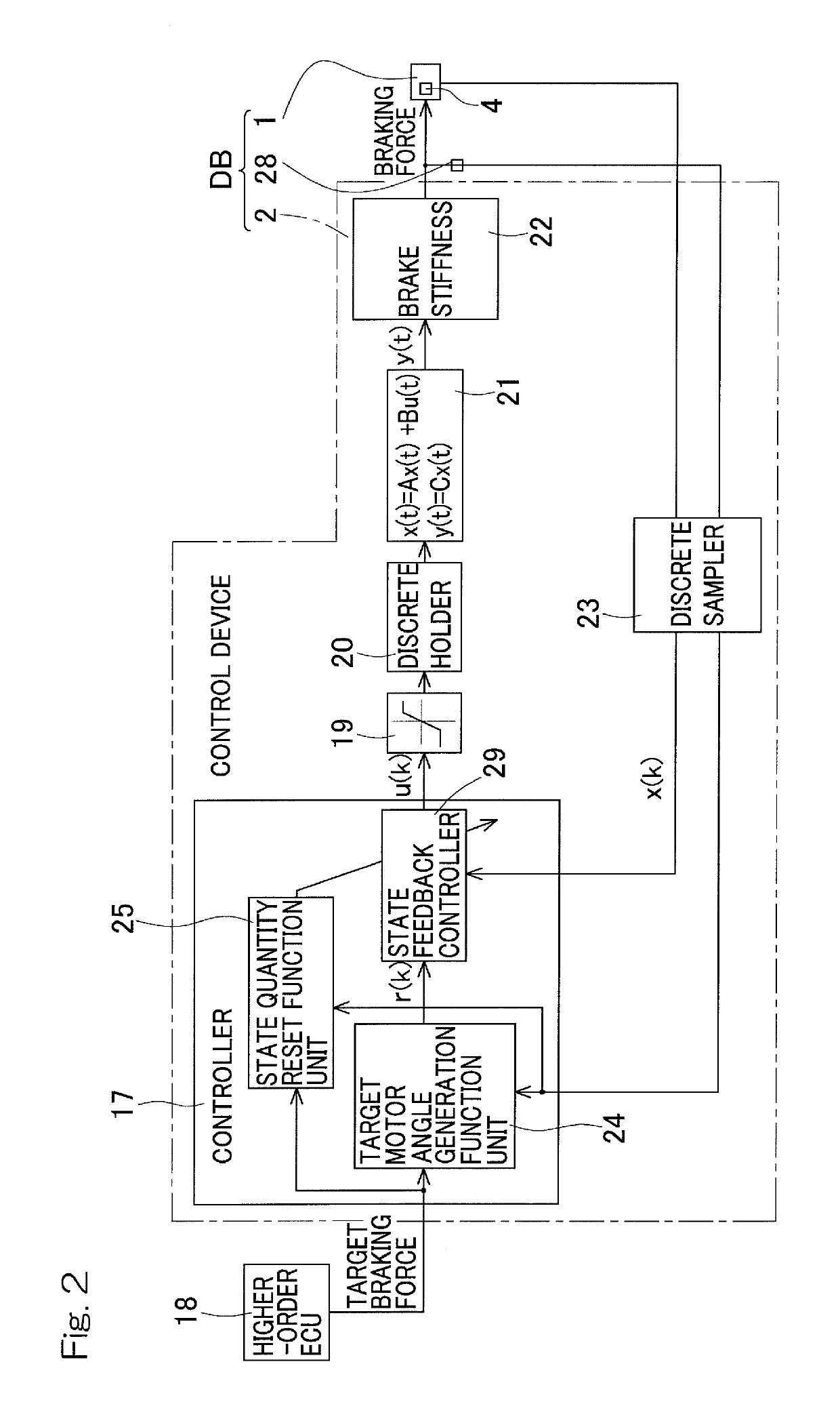
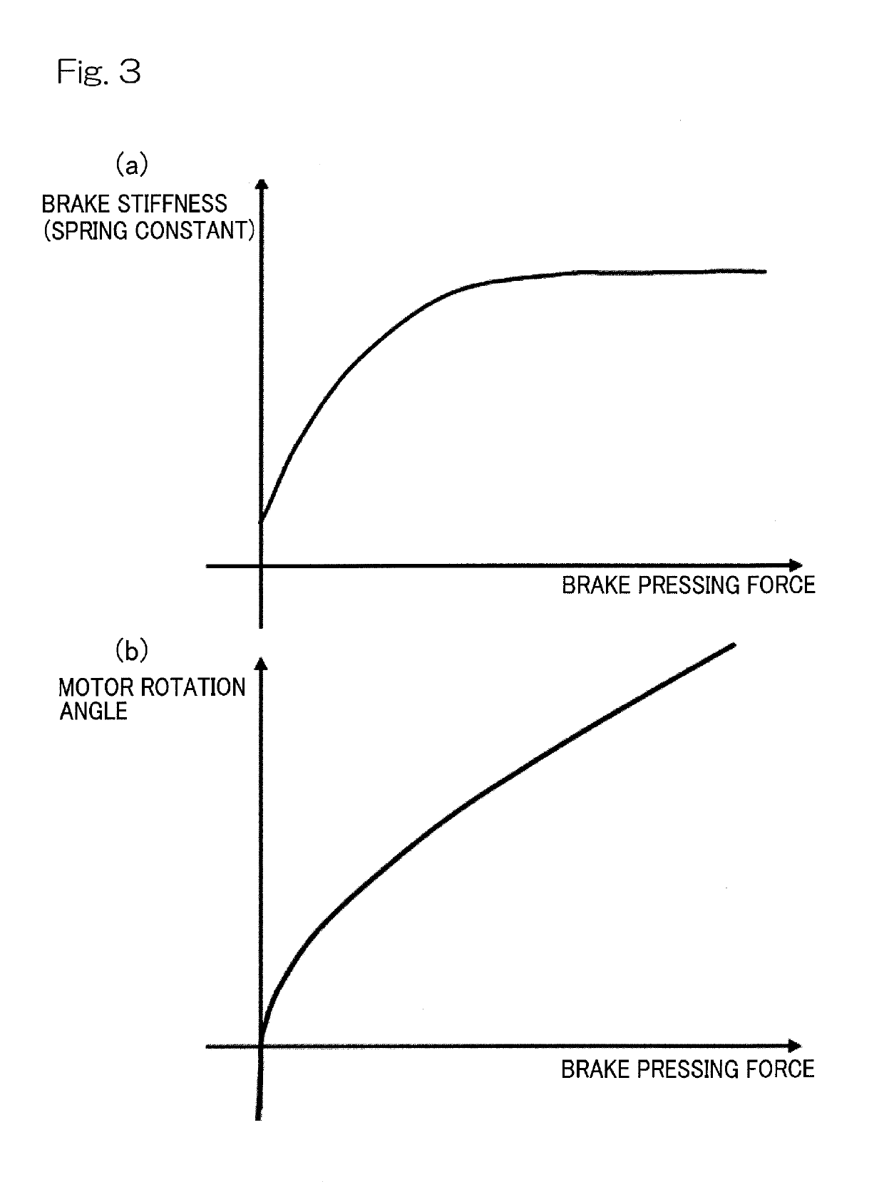
[0017]In this configuration, the control device 2 controls the electric motor 4 to perform a control (hereinafter, referred to as “follow-up control”) for causing the braking force to follow the target braking force. The control device 2 has the control system in which the motor rotation angle is included in the state quantity in the follow-up control, and a linear control system can be thus obtained. Therefore, as compared to a conventional art in which a control parameter includes a non-linear spring constant formed of stiffness of an electric brake device, the control system can be more easily designed.
[0018]Since the control device 2 has the control system in which the motor rotation angle is included in a state quantity in the follow-up control, a problem arises that a value of the motor rotation angle becomes very large. However, the state quantity reset function unit 25 resets the motor rotation angle that is the state quantity as described below, and the problem can be thus prevented. In the control device 2, the state quantity reset function unit 25 resets at least the motor rotation angle to the predetermined value, on the basis of the predetermined condition using at least one of the target braking force, the estimated value of the braking force, the amount of change of the target braking force, the amount of change of the estimated value of the braking force, and the deviation between the target braking force and the estimated value of the braking force. Thus, increase of calculation load can be inhibited, and occurrence of overflow of a variable can be prevented. The state quantity reset function unit 25 resets the motor rotation angle when a condition that is less likely to influence brake feeling is satisfied as the predetermined condition. Therefore, even if an operation amount is varied according to the motor rotation angle being reset, a driver is less likely to perceive brake feeling worse.
[0024]In a case where the absolute value of the deviation between the target braking force and the estimated value of the braking force is greater than or equal to a threshold value, it can be considered that, by, for example, braking operation being abruptly performed, the electric brake device DB is operating at a very high speed. In this case, even if the operation amount is varied according to the motor rotation angle that is the state quantity being reset, a driver is less likely to perceive brake feeling worse. When the above-described deviation is great, it can be considered that motor output saturation is highly likely to occur. In such a case, it can be considered that varying of an operation amount itself according to the state quantity being reset, is less likely to occur.

Problems solved by technology

However, in designing of a servo control device of an electric motor, in a case where a target value is a required braking force, and a control variable is an estimated braking force, since a control parameter includes a non-linear spring constant κ formed of stiffness of the electric brake device as indicated in the following equation, a problem arises that designing of a control system becomes difficult.
However, when the motor angle is included in the calculation, a value of the motor angle is likely to become very large, and a problem arises that increase of calculation load or overflow of a variable occurs more frequently.
However, due to, for example, digits after the decimal point being rounded down, when x(t) is reset, the value of the operation amount u(k) varies, and an electric actuator may operate in an undesired manner.
When this problem arises in the electric brake device, braking shock, worse operation noise, or the like are generated, whereby brake feeling may become worse.

Method used


Image

  • Electric brake device
  • Electric brake device
  • Electric brake device

Examples


Embodiment Construction

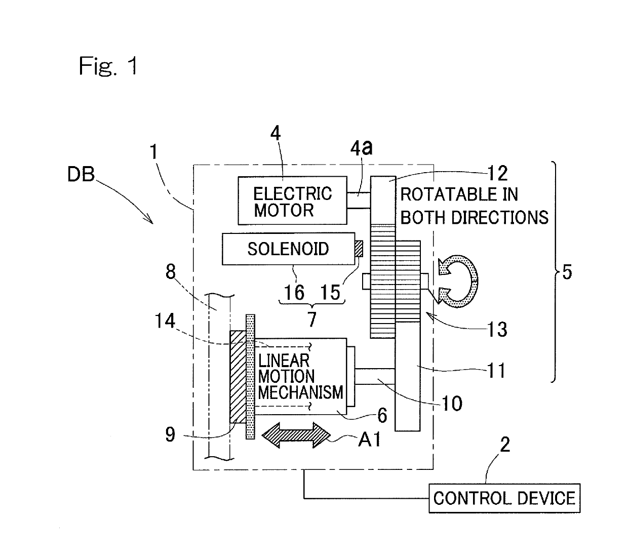
[0037]An electric brake device according to an embodiment of the present invention will be described with reference to FIGS. 1 to 5. As shown in FIG. 1, an electric brake device DB includes an electric actuator 1, a control device 2, and a braking force estimation unit 28 (FIG. 2). Firstly, the electric actuator 1 will be described.

[0038]The electric actuator 1 includes: an electric motor 4; a speed-reducing mechanism or speed reduction gear 5 that reduces a speed of rotation or number of rotation per unit time of the electric motor 4; a linear motion mechanism 6; a parking brake mechanism 7 that is a parking brake; a brake rotor 8; and a friction member 9. The electric motor 4, the speed-reducing mechanism 5, and the linear motion mechanism 6 are incorporated in, for example, a not-illustrated housing. The brake rotor 8 rotates integrally with a not-illustrated wheel, and may be a disc-type one or a drum-type one. The friction member 9 is implemented by a brake pad, a brake shoe, o...


PUM


Abstract

An electric brake device includes: a brake rotor; a friction member; friction member contactor; an electric motor; braking force estimation unit; and a control device. The control device has a control system in which a motor rotation angle of the electric motor is included in a state quantity in a control computing of a follow-up control. The control device includes a state quantity reset function unit that resets at least the motor rotation angle to a predetermined value, on the basis of a predetermined condition using at least one of a target braking force, an estimated value of a braking force, an amount of change of a target braking force, an amount of change of an estimated value of a braking force, and a deviation between a target braking force and an estimated value of the braking force.

Description

CROSS REFERENCE TO THE RELATED APPLICATION[0001]This application is a continuation application, under 35 U.S.C. § 111(a), of international application No. PCT / JP2016 / 058611, filed Mar. 17, 2016, which is based on and claims Convention priority to Japanese patent application No. 2015-63675, filed Mar. 26, 2015, the entire disclosure of which is herein incorporated by reference as a part of this application.BACKGROUND OF THE INVENTIONField of the Invention[0002]The present invention relates to an electric brake device, and relates to a technique that allows a control system to be easily designed without making brake feeling worse.Description of Related Art[0003]For the electric brake device, the following techniques are suggested.[0004]1. An electric linear actuator in which a planetary roller screw mechanism is used (Patent Document 1).[0005]2. An actuator, for an electric brake, which converts rotary motion of a motor to linear motion through a linear motion mechanism by pressing a ...

Claims


Application Information

Patent Timeline
Patent Type & Authority Patents(United States)
IPC IPC(8): B60T13/74F16D65/18
CPCB60T13/746F16D65/18B60T13/74B60T13/741B60T13/662B60T17/22F16D66/00F16D2066/005B60T8/171
Inventor MASUDA, YUI
Owner NTN CORP
Learn More