[0005]In an electric automobile equipped with large-output motors, a power control unit handles a large electric power. As electric power handled by the power control unit becomes larger, a load of every power semiconductor element becomes greater. In order to reduce a load per power semiconductor element, two or more power semiconductor elements are connected in parallel in some cases. Alternatively, in an electric automobile in which multiple motors are installed, an inverter circuit and others are required in each of the motors, and thus more power semiconductor elements are required. That is, there are some electric automobiles that require many power modules accommodating power semiconductor elements. As the number of power modules that are stacked in the stacked unit becomes increased, a length in the stacking direction of the stacked unit becomes longer. If the stacked unit and the reactors are arranged in the stacking direction, the entire length of the power control unit becomes longer. When the power control unit is arranged in the vehicle such that the stacking direction of the power modules and the coolers is directed toward the vehicle-longitudinal direction, a great limitation to installation might be caused to the power control unit extending in the longitudinal direction. It has been desired a technique to reduce a length in the vehicle-longitudinal direction of a power control unit installed in a vehicle.
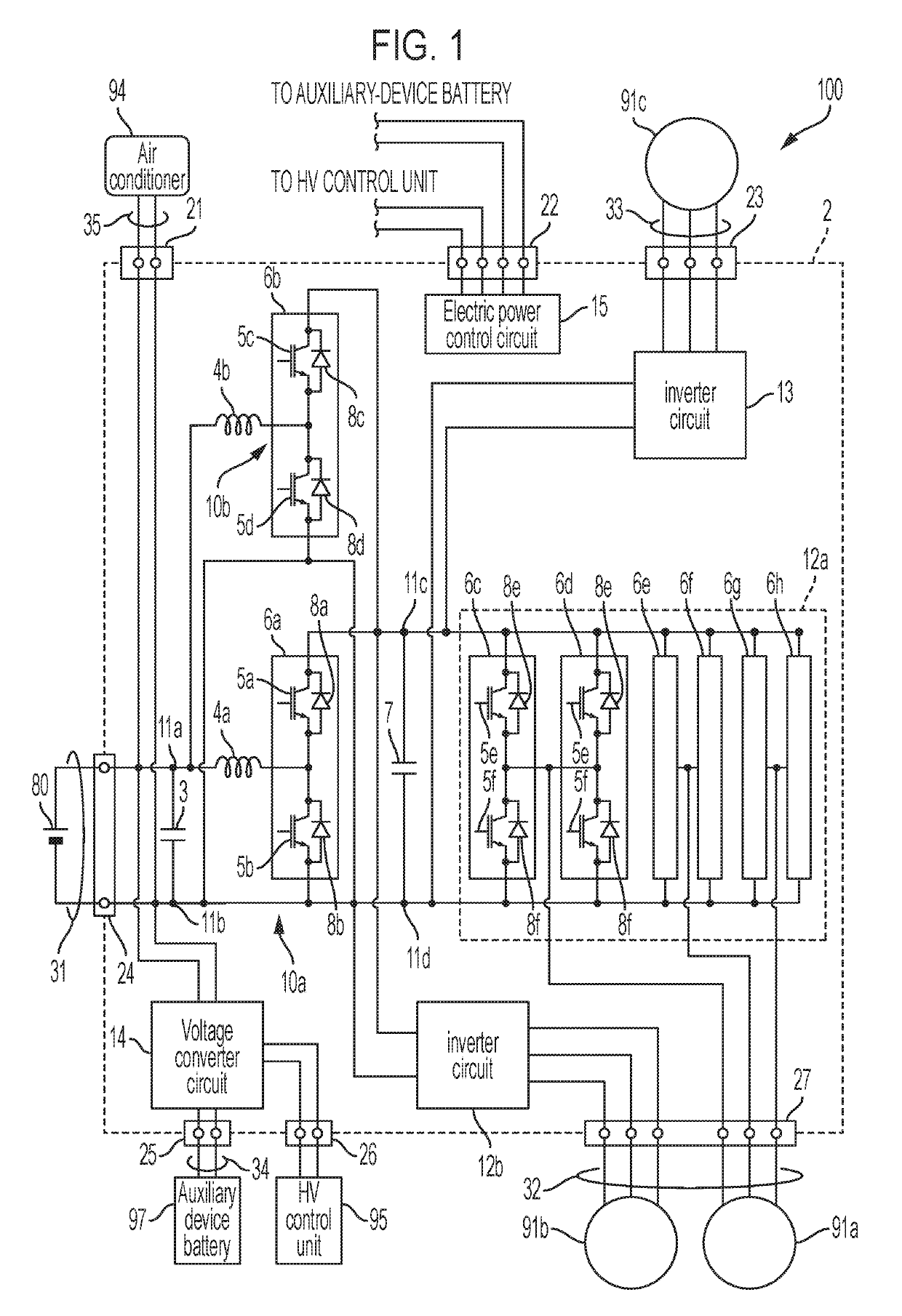
[0007]In the above vehicle, the power control unit may include first voltage converter circuits and inverter circuits. The first voltage converter circuits may be configured to boost voltage of the electric power source. The inverter circuits may be configured to convert output electric power of the first voltage converter circuits to alternating current. A first capacitor may be connected between a first positive-electrode terminal and a first negative-electrode terminal that are located on the electric power source side of the first voltage converter circuits. A second capacitor may be connected between a second positive-electrode terminal and a second negative-electrode terminal on the inverter circuit side of the first voltage converter circuits. The first capacitor and the second capacitor may be disposed, in the case, on the same side in the vehicle-width direction so as to be adjacent to the stacked unit. In the above vehicle described in JP 2015-204688 A, the first capacitor is disposed adjacent to the stacked unit in the vehicle-width direction, and the stacked unit, the reactors, and the second capacitor are arranged in the stacking direction. The first capacitor and the second capacitor are arranged on the same side in the vehicle-width direction to be adjacent to the stacked unit, to thereby further reduce the length in the vehicle-longitudinal direction of the power control unit installed in the vehicle.
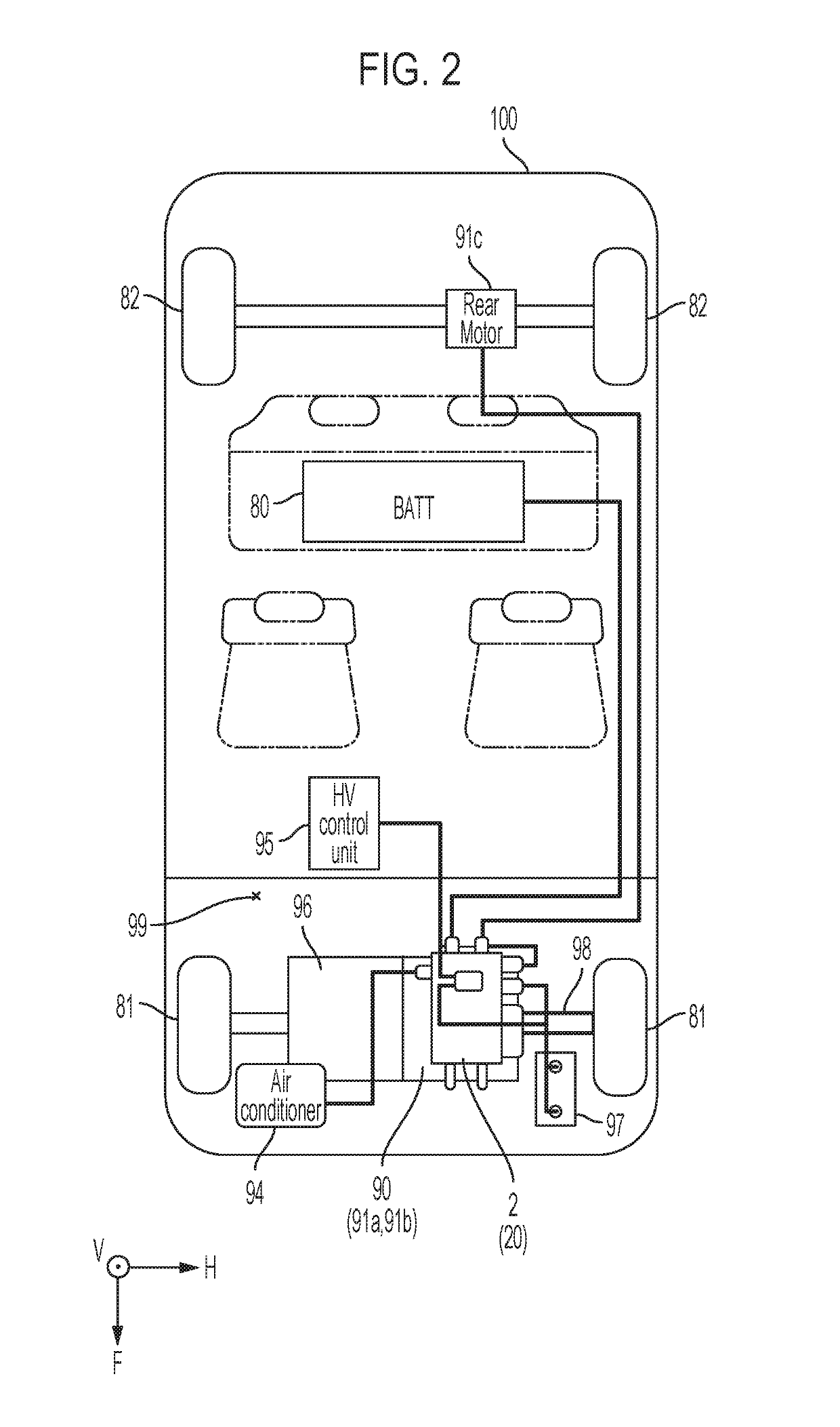
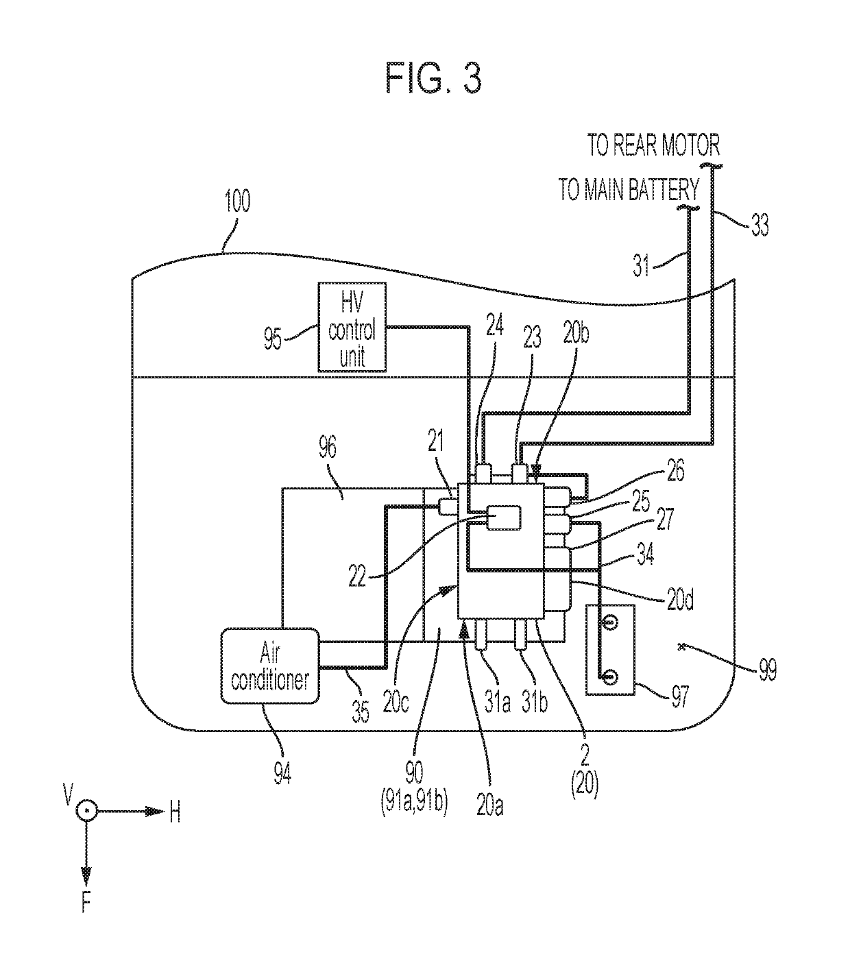
[0008]The above vehicle may further include: a rear motor; and an auxiliary-device battery. The motors may be for driving front wheels. The motor housing may be installed in a front compartment of the vehicle. The power control unit may further include: a rear inverter circuit; and a second voltage converter circuit. The rear inverter circuit may be configured to convert direct current electric power to drive electric power of the rear motor for driving rear wheels. The second voltage converter circuit may be configured to step down the voltage of the electric power source and provide this voltage to the auxiliary-device battery. The second voltage converter circuit may be disposed rearward of the reactors in the case. A rear motor connector connected to a rear motor power cable that sends electric power to the rear motor may be provided on a surface of the case, and the surface provided with the rear motor connector may be directed toward the rearward direction of the vehicle. An auxiliary-device battery connector connected to an auxiliary-device battery power cable that sends electric power from the second voltage converter circuit to the auxiliary-device battery may be provided on a surface of the case, and the surface provided with the auxiliary-device battery connector may be directed toward the vehicle-width direction. By providing the rear motor connector to the rear surface of the case, it is possible to shorten the rear motor cable. In addition, by providing the rear motor connector, which is provided on the lateral side surface of the case in the related art, to the rear surface, it is possible to provide the auxiliary-device battery connector to the lateral side surface of the case. With this, it becomes easier to connect the second voltage converter circuit and the auxiliary-device battery connector that are disposed at rearward positions inside the case. As a result, it is possible to eliminate wiring for connection of the circuit board located at an upper position in the case and the low-voltage connector to the second voltage converter circuit.
[0009]The above vehicle may further include an air conditioner. The main power connector connected to the main power cable that supplies the electric power of the electric power source to the power control unit may be provided on a surface of the case, and the surface provided with the main power connector may be directed toward the rearward direction of the vehicle. An air-conditioner connector may be provided at a rearward position of a side surface of the case, and the side surface provided with the air-conditioner connector may be directed toward the vehicle-width direction and may be located closer to the main power connector. The air-conditioner connector may be electrically connected to the main power connector inside the case. The air-conditioner connector may be connected to an air-conditioner cable that supplies the electric power of the electric power source to the air conditioner. The main power connector and the air-conditioner connector are disposed to be adjacent to each other with the corner of the power control unit interposed therebetween, to thereby shorten the connection path between the both.
[0010]In the above vehicle, the main power connector connected to the main power cable that supplies the electric power of the electric power source to the power control unit may be provided on a surface of the case, and the surface provided with the main power connector may be directed toward the rearward direction of the vehicle. The first capacitor may be disposed frontward of the main power connector as viewed from above, and the first capacitor and the main power connector may be connected to each other. With this configuration, it is possible to shorten the connection path between the first capacitor and the main power connector.
[0011]In the vehicle, the reactors may be disposed under the stacked unit. The power control unit may further include a circuit board on which an electric-power control circuit is mounted may be disposed above the stacked unit. The stacked unit and the reactors, which give off a large amount of heat, are used along with coolers using liquid coolant in some cases. The circuit board on which electric-power control circuits are mounted is disposed above the reactors and the stacked unit, to thereby suppress the circuit board from coming into contact with the liquid even if the liquid leaks out from the coolers. The circuit board is disposed at an upper position in the space inside the case (immediately under the upper cover), it is possible to facilitate the replacing work and the maintenance work of the circuit board.

