Door lock with integrated door position sensor

a door lock and position sensor technology, applied in the field of door locks with integrated electronics, can solve the problems of affecting the installation of external door position sensors, affecting the safety of doors, etc., and achieve the effect of maximizing the magnetic field strength

Active Publication Date: 2019-10-08
SARGENT MANUFACTURING CO INC
View PDF23 Cites 4 Cited by
  • Summary
  • Abstract
  • Description
  • Claims
  • Application Information

AI Technical Summary

Benefits of technology

[0021]It is another object of the present invention to provide a door strike that uses more available space than current designs to increase the magnetic field.
[0029]In an alternative embodiment, the sensor is spring mounted to eliminate all mounting tolerances and ensure that the sensor is maximally forward and flush against the back of the non-magnetic faceplate.

Problems solved by technology

Typically, if the door is locked, it would not allow access.
However, using a sensor that is external to the lock makes it difficult for the information about the monitored door position to be directly used by the door lock electronics and / or the central control system for the door locks.
Further, an external door position sensor is more difficult to install.
It is more easily damaged or tampered with.
One problem with integrating a door position sensor into a lock is the limited space available for the sensor.
However, this is a less secure lock design than one that includes the deadbolt and, as such, it is not suitable for high security applications.
However, it is often difficult to integrate a magnetic sensor into a lock because lock mechanisms typically have many components made of steel, iron or other magnetic materials, all of which potentially interfere with the operation of a magnetic sensor.
However, the door strike is typically made of steel, which can interfere with the magnetic field.
These openings severely limit the space available for the magnet.
It would be undesirable, in any case, to expand the size of the strike, as this may indicate the presence of a door position sensor to unauthorized persons.
As indicated above, these space limitations have heretofore typically required that the deadbolt be omitted when installing a door position sensor.
A related problem is that a mortise lock typically has a case and a decorative “faceplate.” The front edge of the mortise lock case (the “front plate”) and the decorative faceplate are both typically made of magnetic materials, which cause problems with magnetic sensor designs.
The combination of limited space with the necessity to “hide” the magnets, coupled with the problems of magnetic materials have all made it very difficult to provide a reliable door position sensor for locks, particularly for mortise locks having a deadbolt.
The problem is particularly acute when the door is hung poorly with a gap between the door and the strike plate that is greater than usual.
This weakens the magnetic field extending from a magnet in the strike plate towards the lock to the point that a magnetic sensor located in the lock may no longer be able to detect the weakened field when the door is closed.
This results in an erroneous indication that the door is open.
Although it might seem to be desirable to extend the sensor into the gap area, this cannot be done, as it would make the sensor visible, subject to attack and damage and potentially would interfere with operation of the door.
With respect to bored locks, the small size of the strike (as compared to the strike for a mortise lock with a deadbolt) creates similar problems, particularly for bored in locks having a two piece front plate similar to the faceplate / front plate design for a mortise lock.

Method used


Image

  • Door lock with integrated door position sensor
  • Door lock with integrated door position sensor
  • Door lock with integrated door position sensor

Examples


Embodiment Construction

)

[0045]In describing the preferred embodiment of the present invention, reference will be made herein to FIGS. 1-14 of the drawings in which like numerals refer to like features of the invention.

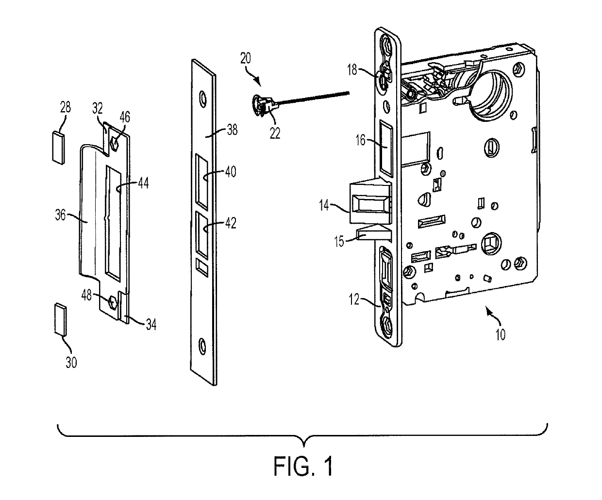
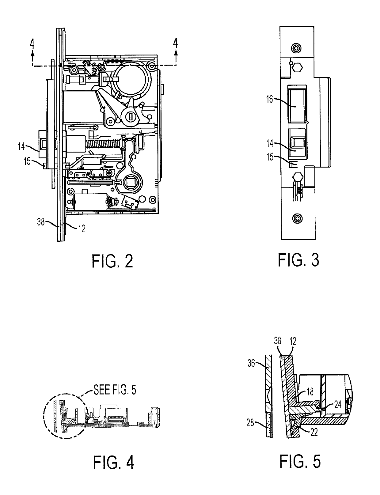
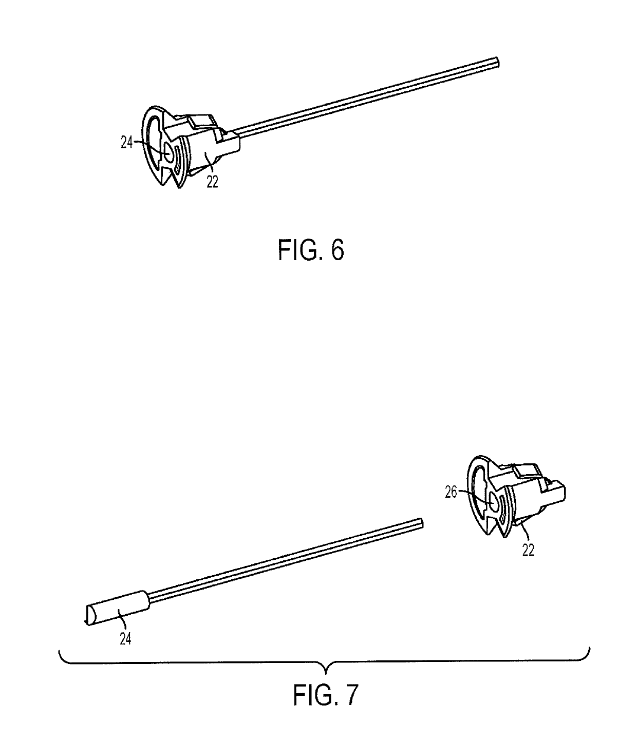
[0046]Referring to FIG. 1, a mortise lock 10 includes a front plate 12. A latchbolt 14, a guard bolt 15 and a deadbolt 16 are operable through corresponding openings in the faceplate. The faceplate 12 includes a beveled mounting hole 18 that receives a magnetically actuated door position sensor 20. Referring to FIGS. 6 and 7, the door position sensor 20 includes a sensor mount 22, preferably of plastic or other non-magnetic material, and a magnetically actuated sensor 24, which my be a reed switch, a Hall effect sensor or other magnetically operated sensor device.

[0047]The sensor mount 22 is shaped to fit into the beveled mounting opening 18 in the faceplate 12. Preferably, the sensor mount 22 snaps into the beveled opening. The faceplate 12 may be of a magnetic material, which allows a conv...


PUM


Abstract

A door lock with integrated door position sensor includes rectangular magnets positioned behind the door strike to maximize magnetic field strength in available space limited by industry-standard dimensions for the door strike. A beveled or stepped mounting opening for the sensor is formed in a front plate of the door lock and behind a non-magnetic faceplate. The shape of the mounting opening allows the magnetic field to penetrate deeply through the faceplate and front plate to actuate the door position sensor. The sensor may be used in mortise locks or bored locks. In an alternative embodiment, the sensor is spring mounted to eliminate all mounting tolerances and ensure that the sensor is maximally forward and flush against the back of the non-magnetic faceplate.

Description

BACKGROUND OF THE INVENTION[0001]1. Field of the Invention[0002]The present invention relates to door locks with integrated electronics. More particularly, the present invention relates to door locks with an integrated sensor to detect whether the door in which the lock is installed is open or closed.[0003]2. Description of Related Art[0004]In recent years, door locks have increasingly been designed with integrated electronics, actuators and sensors. Door locks of this type are typically used in public buildings, businesses and high-end residential applications where it is desired to monitor door usage, detect unauthorized entry and the like. The lock electronics may record or use the monitored data at the lock, or it may send the data for use at another location through a wired or wireless connection.[0005]Generally electronic locks of this type monitor the position of one or more internal lock components. For example, a switch or sensor inside the lock may detect when a latchbolt ...

Claims


Application Information

Patent Timeline
Patent Type & Authority Patents(United States)
IPC IPC(8): E05B47/00E05B55/00E05C1/00
CPCE05B47/0038E05B55/005E05C1/004E05B2047/0068Y10T292/097E05B45/00E05B47/00E05C1/12
Inventor NUNEZ, PAULBOGDANOV, VICTORWONG, WAI P.
Owner SARGENT MANUFACTURING CO INC
Why Eureka
Try Eureka