
Magnetic field probe station

A magnetic field probe and probe technology, which is applied in the field of magnetic field probe stations, can solve the problem that the probe station is difficult to realize multi-dimensional magnetic fields, and achieve the effect of saving space and avoiding interference with magnetic field signals.

Pending Publication Date: 2020-01-31
致真精密仪器(青岛)有限公司
View PDF0 Cites 1 Cited by
  • Summary
  • Abstract
  • Description
  • Claims
  • Application Information

AI Technical Summary

Problems solved by technology

In particular, when using a high magnification objective lens for imaging measurement, the distance between the sample and the objective lens needs to be very close (that is, the sample must be located at the focal point of the objective lens imaging), which is a compatible configuration of the magnetic field generating device, electrical testing device and optical module bring challenges
[0003] The current various probe stations are difficult to realize the integration of multi-dimensional magnetic fields, DC / AC probes and high-magnification microscopic imaging

Method used


Image

  • Magnetic field probe station
  • Magnetic field probe station
  • Magnetic field probe station

Examples


Embodiment Construction

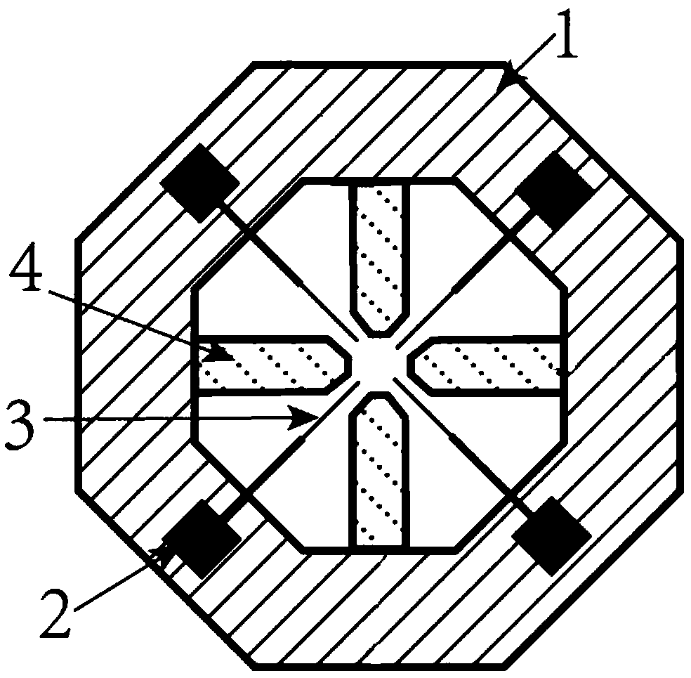
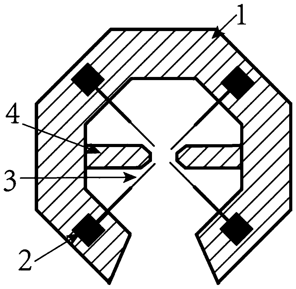
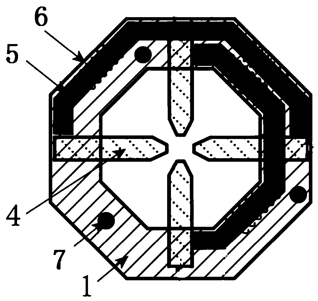
[0027] The present invention will be described in detail below with reference to the accompanying drawings and specific embodiments, a magnetic field probe station, such as figure 1 , image 3 As shown, it includes: a table top 1, at least a pair of probe bases 2, at least a pair of electrical probes 3, at least a pair of in-plane magnetic poles 4, a magnetic conductive structure 5, an excitation coil 6, an excitation coil power supply unit and a table support device 7;

[0028] The table top 1 is an annular structure, the in-plane magnetic pole 4 is fixed on the inner side of the lower annular structure of the table top 1, the probe base 2 is fixed on the upper surface of the table top 1, the electrical probe 3 is installed on the probe base 2, and the magnetic conductive structure 5 Fixed on the lower surface of the table, the excitation coil 6 is wound on the surface of the magnetic conductive structure 5, the excitation coil power supply unit supplies power to the excitati...


PUM


Abstract

The invention proposes a magnetic field probe station. The magnetic field probe station comprises a tabletop, at least one pair of probe seats, at least one pair of electrical probes, at least one pair of in-plane magnetic poles, a magnetic conduction structure, an excitation coil, an excitation coil power supply unit and a tabletop support device. Compared with a traditional probe station structure, the magnetic conduction structure and the excitation coil are placed below the tabletop, and no interference to the arrangement of the electrical probes and an optical module is caused; moreover,the space is saved, and a sample table and a vertical magnet below the tabletop can be allowed to be arranged; and when an objective is rotated and switched, the situation that the objective in the optical module touches the coil due to excessively large size of the excitation coil is prevented. A magnetic pole fixing mode proposed by the invention is set to be a mode of an adjustable distance between the magnetic poles, a distance between the magnetic poles is set according to test demand, different test demands are adapted, and the magnetic field probe station also can be cooperatively usedwith a magneto-optical Kerr microscope.

Description

Technical field: [0001] The invention belongs to the technical field of testing and measurement, in particular to a magnetic field probe station. Background technique: [0002] Measurement systems capable of integrating magnetic, electrical and optical modules are of great use for the testing of electronic devices. However, because the magnetic field generation module (including electromagnet), electrical module (including DC / high frequency AC probe, etc.), and optical detection module (including objective lens, etc.) all need to occupy space and are incompatible, it brings great difficulty to system integration . In order to achieve a higher magnetic field, it is generally necessary to use a ferromagnetic material as a magnetic pole or magnetic shoe, and the magnetic pole or magnetic shoe needs to be close to the sample. At the same time, in order to make the system compatible with the needs of optical testing, there needs to be enough space above the probe station near t...

Claims


Application Information

Patent Timeline
Patent Type & Authority Applications(China)
IPC IPC(8): G01D21/02
CPCG01D21/02
Inventor 张学莹王麟赵巍胜欧阳玉东
Owner 致真精密仪器(青岛)有限公司
Learn More