Detection device

a detection device and detection technology, applied in the field of detection devices, can solve the problems of increasing the proportion of dead time (time), reducing the efficiency of the overall process, and high effective manual scanning time-consuming, so as to reduce vignetting and keep the size of the optics

Active Publication Date: 2019-10-08
QINETIQ LTD
View PDF12 Cites 1 Cited by
  • Summary
  • Abstract
  • Description
  • Claims
  • Application Information

AI Technical Summary

Benefits of technology

[0012]By using a prism having at least a portion of the first surface having a varying angle with respect to the second surface it is possible to create a continuous linear scan using a single beam, thus removing the issues created by dead time and minimising signal to noise ratio effects. Signal quality therefore remains high when compared with using many individual beams to perform a scan.
[0014]Preferably, the first surface comprises an interface between the second position on the first surface and the first position on the first surface where the angle θ changes sharply, thus acting as a flyback at the end of the vertical scan. Thus, this provides a scan from a first position on the target to a second position during movement of the prism from first to the second position. Alternatively the angle θ may increase from a minimum to a maximum value and then back again to the minimum value over one rotation of the prism. This provides a scan from the first position, to the second position and back to the first during a full rotation of the prism. This has a benefit in that no discontinuous interface is formed in the first surface, but this arrangement leads to a steeper pitch to the spiral formed between the edge of the first surface and the edge of the second surface and thus increases optical aberration. The aberration increases with increased curvature across that part of the prism that is, at any given instant, involved in refracting incoming radiation.
[0021]Preferably the device is arranged to receive millimeter wave radiation, that is fed through the prism, where the received radiation is emitted by, or reflected from the target which has emanated from the surrounding environment, and does not comprise of radiation transmitted by the device through the prism. Thus, such devices may be passive devices, in that they rely on naturally occurring millimeter wave radiation, or they may be passive devices wherein the background radiation levels are augmented by one or more non-coherent millimeter wave noise sources, such as heaters, white noise generators, or the like. Such passive systems simplify the system design, and also provide reassurance that the systems are safe to use from the point of view of targets being subject to radiation.
[0033]Advantageously, the beam of electromagnetic radiation is a collimated beam. The optical system may be arranged to produce the collimated beam, using, for example, an afocal telescope arrangement. Use of a collimated beam can help to keep the size of the optics down, and also helps to reduce vignetting.
[0038]Preferably, the first surface comprises an interface between the first position on the first surface and the second position on the first surface where the angle θ changes sharply. This interface provides a “flyback” function to the beam, moving the beam from a finishing point of its continuous scan back to a starting point. Continued rotation of the prism causes this scan-flyback process to cycle repeatedly.

Problems solved by technology

Although highly effective a manual scan is time-consuming, since the operator must scan the scene whilst interpreting the sensor response at each position scanned.
This reduces the efficiency of the overall process, which may cause issues in high traffic areas requiring such scans.
Although this arrangement offers several advantages over a two-beam system, it does have the disadvantage that there is an increasing proportion of dead time (time where measurements are not taking place, which occurs when the beam is cut by the transition between two zones) in the scan, as the number of zones increases.
For six beams the reduction is 2.83, and more than six beams becomes impractical due to the requirements placed on the size of the prism.
This can create issues in determining the most appropriate detection algorithm to use to ensure reliability, and so may decrease performance in terms of hit rate and false alarm rate.
Using improved sampling by increasing the number of beams formed that cover a given vertical angle may aid in reducing algorithm-related issues but the increase in the number of beams causes the integration time and signal to noise ratio to worsen yet further.

Method used


Image

  • Detection device
  • Detection device
  • Detection device

Examples


Embodiment Construction

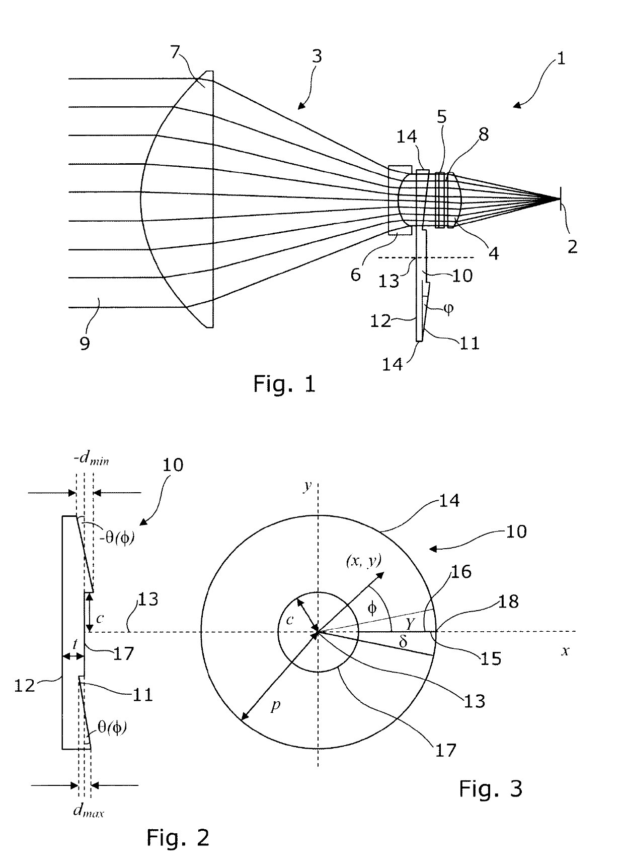
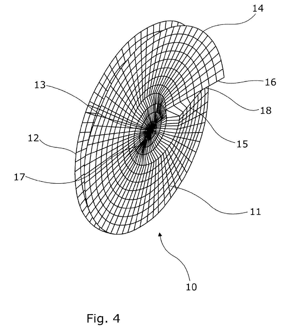
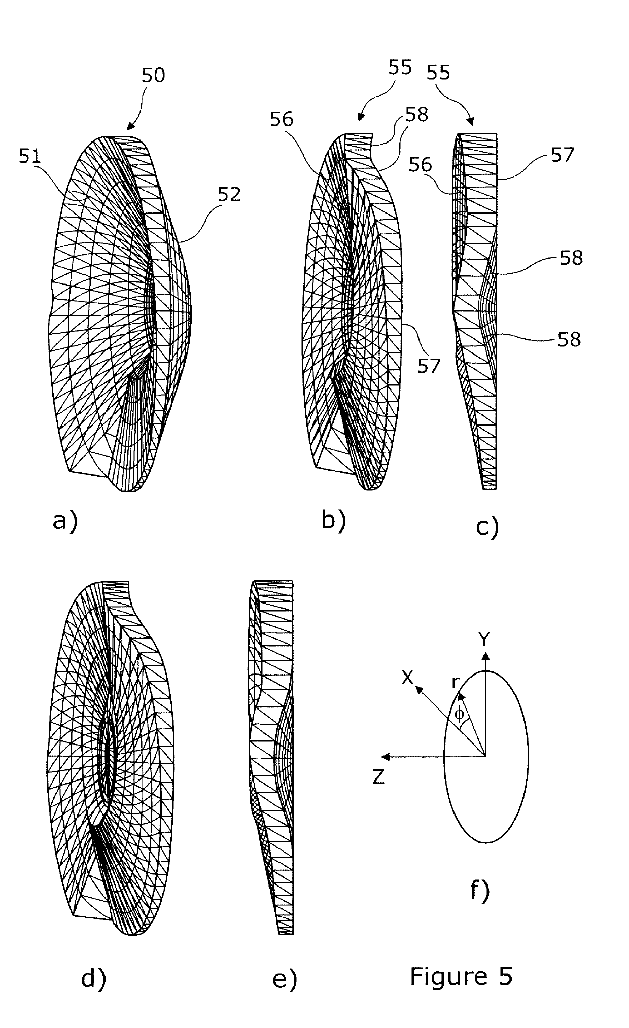
[0057]In order to overcome the issues associated with increased sampling, signal to noise ratio, integration time and algorithm efficiency, the present invention proposes the use of a continuous scan created using a novel prism arrangement, as described in more detail below. A detection device for discriminating between different materials comprises an optical system having at least one optical focussing element and a receiving element. The receiving element is sensitive to millimeter-wave radiation, making it suitable for use in various applications where it is necessary to determine the presence of materials or to distinguish between materials. The optical system is arranged to focus incident energy from a scene onto the receiving element, and comprises a prism element in addition to a focussing element. The prism element has a first surface and a second surface, the first surface being opposite the second surface and positioned at an angle θ to the second surface. The angle θ var...


PUM


Abstract

The present invention discloses a detection device for discriminating between different materials, and a method for doing so. The device comprises an optical system having at least one optical focussing element and a receiving element. The receiving element is sensitive to electromagnetic radiation, typically in the millimeter wave band, and the optical system being arranged to focus incident energy from a scene onto the receiving element. The optical system comprises a prism element having a first surface and a second surface, the first surface being opposite the second surface. At least a portion of the first surface is positioned at an angle θ to the second surface. The angle θ varies between a minimum at a first position on the first surface and a maximum at a second position on the first surface.

Description

FIELD OF THE INVENTION[0001]The present invention relates to a detection device, in particular a detection device for discriminating between different materials, comprising an optical system having at least one optical focussing element, an optical scanning element and a receiving element, wherein the receiving element is sensitive to electromagnetic radiation, preferentially radiation in the millimeter wave band, and where the optical system arranged to focus incident energy from a scene onto the receiving element.BACKGROUND OF THE INVENTION[0002]Millimeter wave radiation systems are commonly used in security settings to identify high risk objects and materials by scanning a scene and using radiation reflected by or emitted by objects within the scene to determine the identity of various objects. Typically such systems produce an image of the radiometric brightness temperature of the scene at frequencies between around 30 GHz up to around 300 GHz. Many such systems tend to be passi...

Claims


Application Information

Patent Timeline
Patent Type & Authority Patents(United States)
IPC IPC(8): G01V8/18G02B26/10G01V8/00
CPCG01V8/005G01V8/18G02B26/108G01N22/00
Inventor ANDERTON, RUPERT NICHOLASHUMPHREYS, RICHARD GEORGE
Owner QINETIQ LTD
Why Eureka
Try Eureka