
Downhole valve system

a valve system and downhole technology, applied in the field of downhole valve systems, to achieve the effect of less reduction

Active Publication Date: 2019-10-15
WELLTEC OILFIELD SOLUTIONS AG
View PDF19 Cites 6 Cited by
  • Summary
  • Abstract
  • Description
  • Claims
  • Application Information

AI Technical Summary

Benefits of technology

The present invention provides an improved system for controlling the flow of fluid in and from a well. The system includes a downhole valve system for controlling the flow of fluid in a way with minimal restrictions in terms of reaction time to changing the inflow from the formation. The system has the advantage of not requiring the need for control lines and also includes a telemetry system for faster response to changes in the flow of fluid. The system allows for greater flow of fluid as compared to traditional intelligent valves and casings and thus provides more options for adjusting the well to a desired production. The system provides faster response to changes in the flow of fluid and is easier to service and optimize. The increased flow of fluid is also advantageous because it avoids the need for additional equipment or decreasing the diameter of the production casing.

Problems solved by technology

However, the cross section of the body of each autonomous operating adjusting device restricts the cross section less than if the controlling means were to be enclosed in the wall of the casing.

Method used


Image

  • Downhole valve system
  • Downhole valve system
  • Downhole valve system

Examples


Embodiment Construction

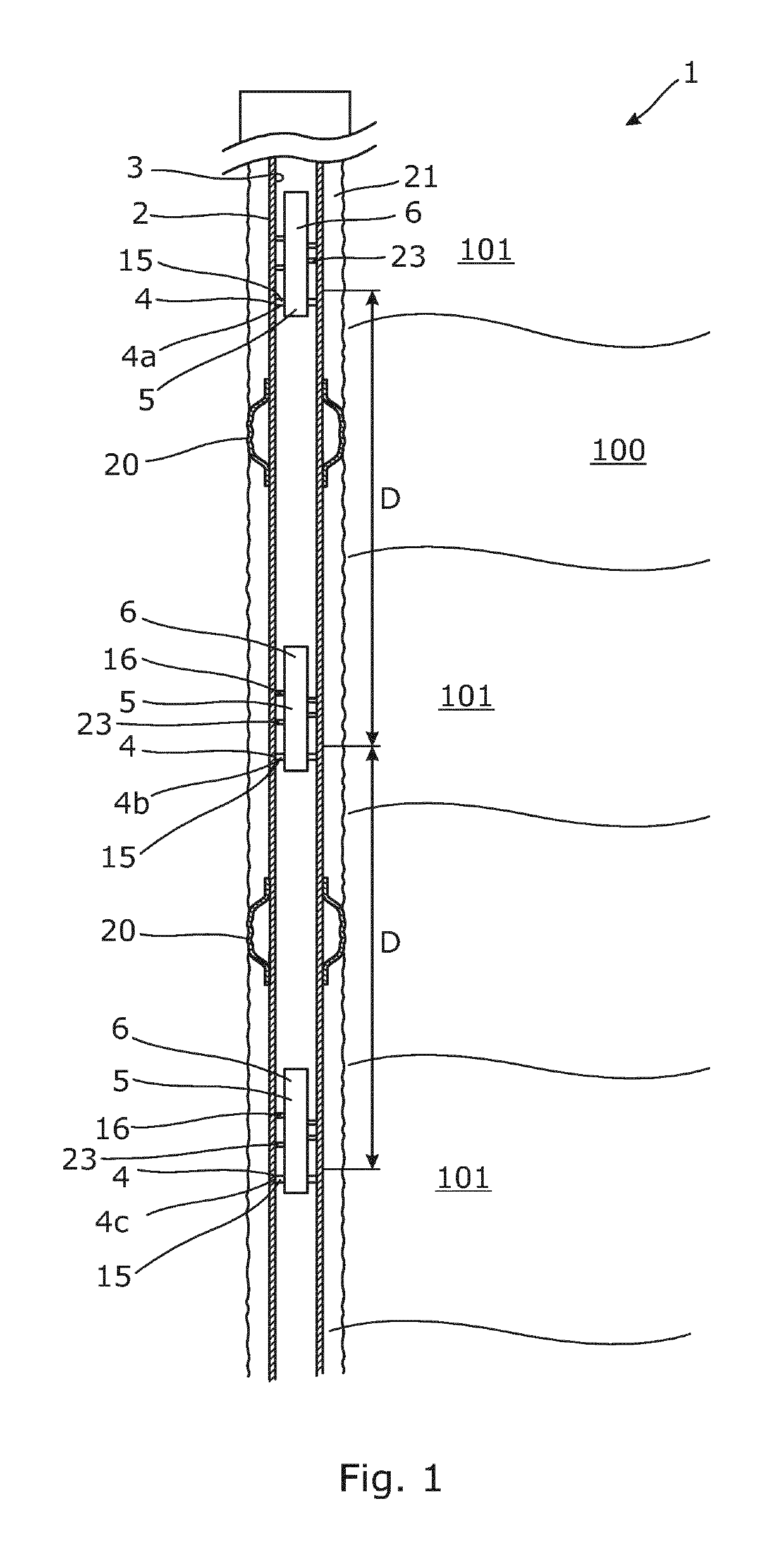
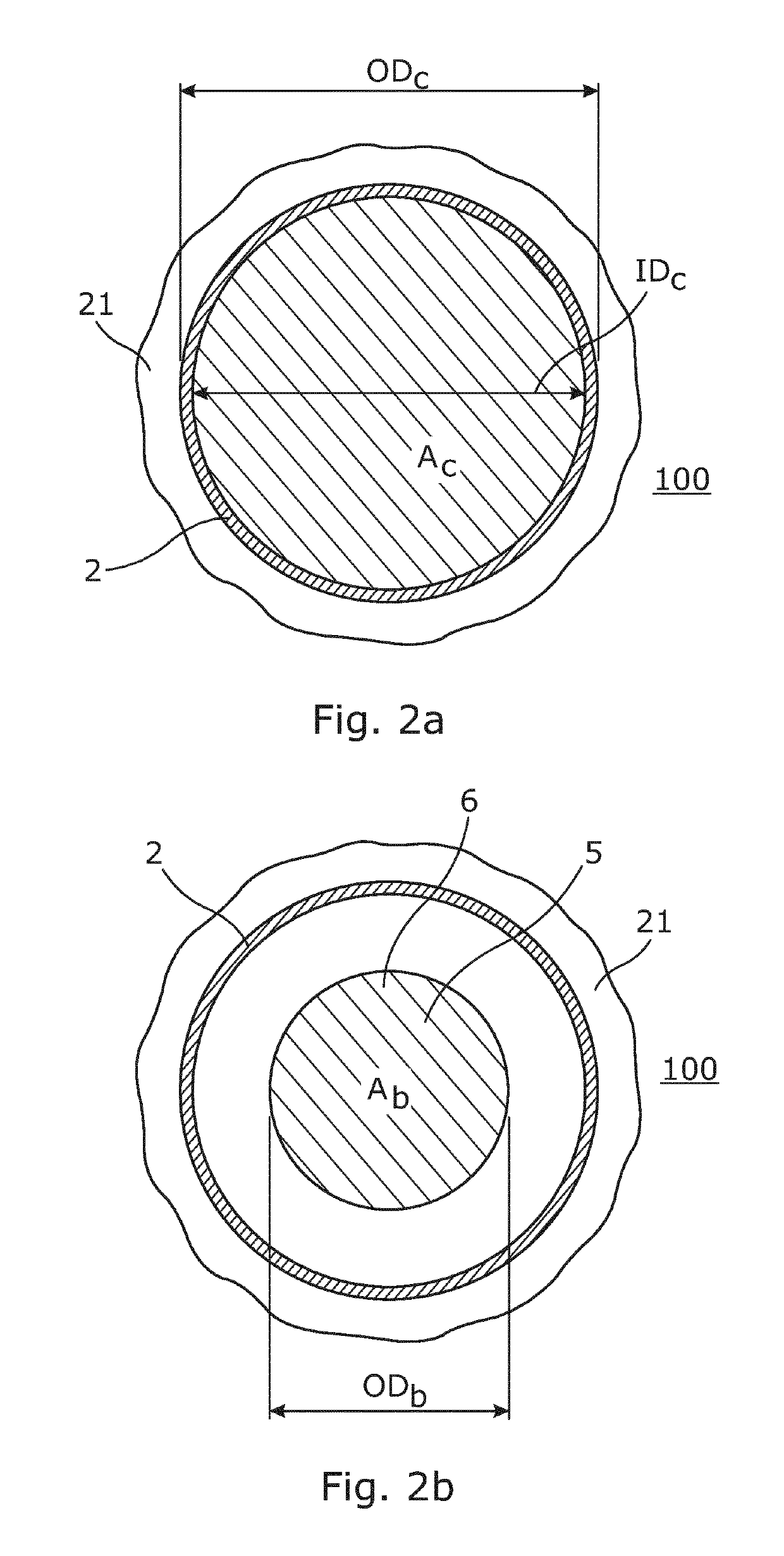
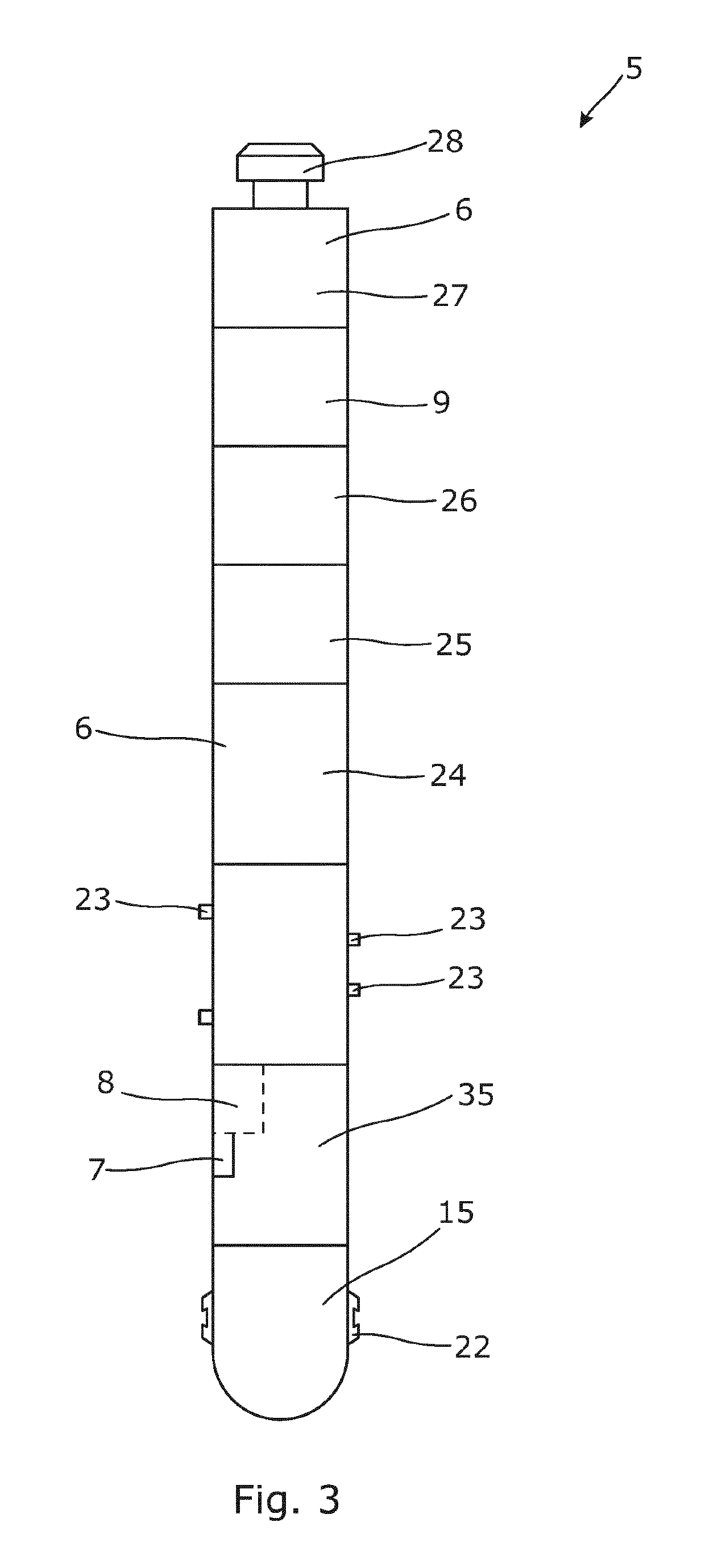
[0076]FIG. 1 shows a downhole valve system 1 for controlling an inflow of a fluid from several production zones 101 in a formation 100. The system 1 comprises a casing 2 arranged in a borehole 21 and annular barriers 20 for isolating the production zones 101. The casing 2 comprises a plurality of valves 4, 4a, 4b, 4c arranged spaced apart from each other by distances for controlling the inflow of the fluid from the production zones 101 and into the casing. The system 1 further comprises a plurality of autonomous operating adjusting devices 5 each controlling one of the plurality of valves 4. Each autonomous operating adjusting device 5 comprises a body 6 having an outer body diameter ODb (shown in FIG. 2). The plurality of autonomous operating adjusting devices 5 are fastened to an inner surface 3 of the casing 2. The autonomous operating adjusting devices 5 are arranged in succession of each other in the casing 2 so that the lowest autonomous operating adjusting device 5 is first a...


PUM


Abstract

The present invention relates to a downhole valve system (1) for controlling inflow of a fluid from and to a formation (100), comprising a casing (2) having an inner surface (3), an outer diameter (ODc) and an inner diameter (IDc), and a cross section (Ac) defined by the inner diameter, the casing comprising a plurality of valves (4, 4a, 4b, 4c) arranged spaced apart from each other for controlling the flow of the fluid to and from the formation through the casing, and a plurality of autonomous operating adjusting devices (5) each controlling one of the plurality of valves and each autonomous operating adjusting device comprising a body (6) having an outer body diameter (Db) and a body cross section (Ab), the plurality of autonomous operating adjusting devices being fastened inside the casing in order to allow the fluid to flow between the outer body diameter of the body of the autonomous operating adjusting device and the casing. The present invention furthermore relates to a method for controlling an inflow of fluid by controlling a plurality of valves in a downhole valve system according to the present invention.

Description

[0001]This application is the U.S. national phase of International Application No. PCT / EP2015 / 068252 filed Aug. 7, 2015 which designated the U.S. and claims priority to EP Patent Application No. 14180326.2 filed Aug. 8, 2014, the entire contents of each of which are hereby incorporated by reference.FIELD OF THE INVENTION[0002]The present invention relates to a downhole valve system and a method for controlling inflow or injection of a fluid to and from a formation.BACKGROUND ART[0003]Valves may be controlled in many ways. Casings comprising means for controlling valves in a well are often referred to as intelligent completions. Conventional intelligent completion makes use of control lines, most often kilometers of hydraulic and / or electrical control lines. These control lines are expensive and frequently malfunctioning due to faulty connections or control line damage. Damaged control lines are practically impossible to repair or replace as they are arranged outside the production c...

Claims


Application Information

Patent Timeline
Patent Type & Authority Patents(United States)
IPC IPC(8): E21B34/14E21B47/10E21B47/06E21B43/14E21B43/12E21B41/00E21B23/03E21B23/02E21B34/06E21B47/18E21B49/08E21B34/00E21B43/26E21B23/01
CPCE21B23/02E21B34/14E21B43/12E21B43/14E21B47/10E21B43/121E21B47/07E21B2200/06E21B23/01E21B34/06E21B47/06E21B47/18E21B49/08
Inventor VASQUES, RICARDO REVESKUMAR, SATISHSTÆHR, LARS
Owner WELLTEC OILFIELD SOLUTIONS AG
Learn More