Boat, assembly and method for handling electronic components

a technology for electronic components and boats, applied in the direction of gripping heads, electronic circuit testing, instruments, etc., can solve the problems of increasing the risk of components being displaced from the boat during handover, unreliable performance of electronic components on the boat, etc., to reduce the air interface, increase thermal conduction, and reduce the effect of air interfa

Active Publication Date: 2019-10-22
RASCO
View PDF7 Cites 0 Cited by
  • Summary
  • Abstract
  • Description
  • Claims
  • Application Information

AI Technical Summary

Benefits of technology

[0029]The method may further comprise the step of, applying a vacuum to the boat when it is positioned in a temperature control station so as to reduce the air interface between the boat and temperature control station thereby increasing thermal conduction between the boat and heating means and / or cooling means. Preferably the vacuum is applied to an under-surface / bottom surface of the boat. Preferably the temperature control station comprises a platform on which the boat can be supported; the temperature of the platform is adjustable using cooling or heating means which are arranged in thermal communication with the platform; when the boat is supported on the platform the temperature of the platform is adjusted to a suitable temperature to achieve heating or cooling of the boat which is supported on the platform. The vacuum applied to the boat pulls the boat towards the platform. This will in turn reduce the air-interface between the boat and the platform so as to improve thermal conduction between the platform and boat.
[0044]The assembly may further comprise, a third vacuum generating means which is fluidly connected to one or more temperature control stations such that it can apply a vacuum to boat(s) positioned in the or each temperature control station, so as to reduce the air interface between the boat(s) and the temperature control station, thereby increasing thermal conduction between the boat and heating means and / or cooling means.
[0045]Each temperature control station may comprises a platform base which is defined by a thermally conductive layer. The third vacuum generating means may be configured such that it can apply a vacuum force to a boat which is located in a respective temperature control station to pull the boat towards the surface of the thermally conductive platform so as to reduce the air interface between the boat and the surface of the thermally conductive platform, thereby increasing thermal conduction between the boat and heating means and / or cooling means.

Problems solved by technology

The holders which mechanically hold the electronic components on the boat provide unreliable performance (for example they do not hold electronic components in the position in which they were originally placed on the boat) and often components become displaced during transport
Moreover there is an increased risk of components becoming displaced from the boat during handover i.e. as a boat begins its transport from the loading area to the next processing station, or as the boat is ending its transport and is being received into next processing station.

Method used


Image

  • Boat, assembly and method for handling electronic components
  • Boat, assembly and method for handling electronic components
  • Boat, assembly and method for handling electronic components

Examples


Embodiment Construction

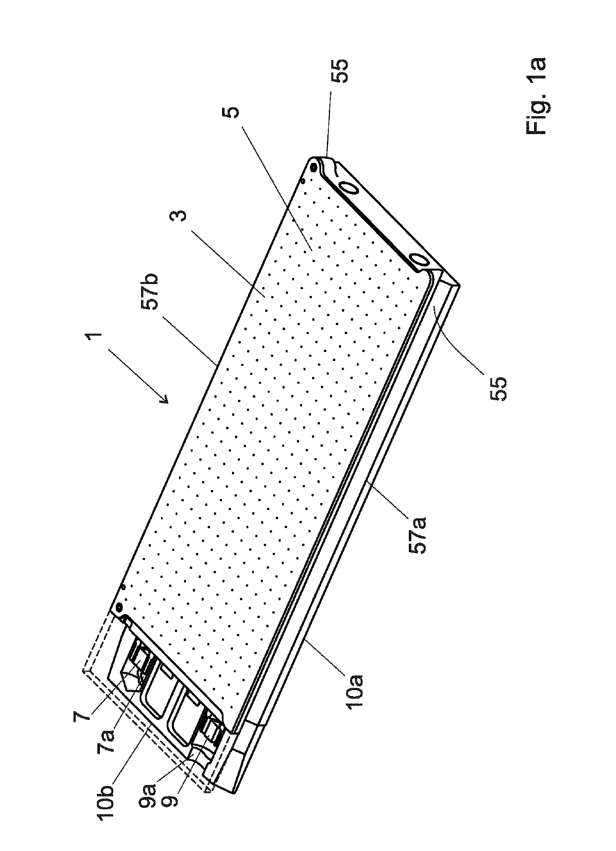
[0066]FIG. 1a provides a perspective view of a boat 1 according to an embodiment of the present invention. The boat comprises, a surface 3 on which a plurality of electronic components (not shown) can be supported. The surface 3 has a plurality holes 5 defined therein through which a vacuum can pass to hold components on the surface 3.

[0067]The boat 1 further comprises a tracks 55 provided along opposite sides 57a,57b of the boat 1 (only the track 55 on side 57a is visible in FIG. 1a). The tracks 55 will be described in more detail below.

[0068]A first vacuum inlet 7 is provided in fluid communication with the plurality of holes 5. The first vacuum inlet 7 can be selectively fluidly connected to a first vacuum generating means that the first vacuum generating means can provide a vacuum at the plurality of holes 5. In this example the first vacuum inlet 7 is configured to have an input 7a located at an under-surface 10a of the boat 1.

[0069]A second vacuum inlet 9 is provided in fluid ...


PUM


Abstract

According to the invention, there is provided a boat which comprises, a surface on which a plurality of electronic components can be supported, the surface having a plurality holes defined therein through which a vacuum can be passed to hold components on the surface; and a first vacuum inlet which is in fluid communication with the plurality of holes, wherein the first vacuum inlet can be fluidly connected to a first vacuum generating means so that the first vacuum generating means can provide a vacuum at the plurality of holes; a second vacuum inlet which is in fluid communication with the same plurality of holes with which the first vacuum inlet is in fluid communication with, wherein the second vacuum inlet can be fluidly connected to a second vacuum generating means so that the second vacuum generating means can provide a vacuum at the plurality of holes. There is further provided a corresponding method of handling electrical components using the boat and a corresponding component handling assembly which comprises one or more boats.

Description

RELATED APPLICATION[0001]This application is a national phase of PCT / EP2015 / 061613, filed on May 26, 2015. The entire content of that application is hereby incorporated by reference.FIELD OF THE INVENTION[0002]The present invention concerns boat for carrying electronic components, wherein the boat has a surface having holes defined therein, on which a plurality of electronic components can be supported, and wherein the boat further comprises a first and second vacuum inlet each of which is in fluid communication with the holes and which can be simultaneously connected to respective first and second vacuum generating means. There is further provided a corresponding method of handling components which uses the boat and a component handling assembly which comprises one or more of the boats.Description of Related Art[0003]Electronic components are typically transported in a processing assembly using carriers such as boats. The electronic components to be transported are loaded on the su...

Claims


Application Information

Patent Timeline
Patent Type & Authority Patents(United States)
IPC IPC(8): B25J15/06G01R31/28H01L21/673H01L21/683H05K13/00B65G29/00B65G47/86B65G47/91H01L21/67
CPCB65G47/91H01L21/67103H01L21/67333G01R31/2808B65G29/00B65G47/847B25J15/0616H05K13/0084H01L21/6838G01R31/2867B65G2201/02Y10S901/40
Inventor CHARPIE, MICHELHITTMANN, RAINERKÜNZLI, SERGESCHAULE, MAXSCHMID, DIETERWIESBÖCK, ANDREASSCHOTTL, THOMAS
Owner RASCO
Why Eureka
Try Eureka