Battery system comprising a control system

a control system and battery technology, applied in the field of battery systems, can solve the problems of compromising charging efficiency, affecting the efficiency of battery operation, and the inability to tailor cell chemistry to be excellent, and achieve the effect of improving battery operation efficiency

Active Publication Date: 2019-10-22
UPGRADE TECH ENG
View PDF9 Cites 3 Cited by
  • Summary
  • Abstract
  • Description
  • Claims
  • Application Information

AI Technical Summary

Benefits of technology

[0010]Therefore, the switching of cell modules allows each sub-battery to become more dominant by switching in more cell modules into the series circuit of the sub-battery, or to become less dominant by switching out cell modules from the series circuit of the sub-battery. Accordingly, the switching allows the relative proportions of power from each of the sub-batteries to be controlled. The control system preferably comprises a battery control unit that is configured to monitor an overall state of charge of the battery system, and the states of charge of the individual sub-batteries, and control the switching of the cell modules based thereon.
[0011]The ability to alter which sub-batteries dominate in the supply of power to the output allows the battery system to operate more efficiently, utilising the discharge characteristics of a particular type of sub-battery in operating situations or environments best suited to that discharge characteristic. Therefore, a plurality of sub-batteries having different discharge characteristics to one another may be implemented, with the sub-battery that has the discharge characteristic most suited to present demands being switched to dominate in the supply of power to the output. The different discharge characteristics correspond to different cell chemistries. More than one sub-battery may be implemented for one or more of the cell chemistry types.
[0013]However, the use of switching according to the present invention enables the share from the high discharge rate cells to be limited, by switching out cell modules from the sub-battery having the high discharge rate cells, and thereby preserving the ability of the battery to deliver a high discharge current when required. For example, during a high discharge current, the high discharge rate capable sub-battery could reduce its number of series connected cell modules, such that its effective off load voltage was reduced. Then, the miss-match in internal resistances of the two sub-battery technologies would allow both sub-batteries to have a more balanced discharge, supplying power to the load proportionally to their capacities. The more series cells that were disconnected by the high discharge rate sub-battery, the more power the high capacity cells would be forced to provide.
[0018]Any cell module within a sub-battery may be switched and cycling modules in and out would also be a process of maintaining cell balancing within a cell module. Cell module switching also provides the ability of the battery pack to isolate defective cells without significantly effecting the overall capacity of the battery.

Problems solved by technology

A single cell chemistry cannot be tailored to be excellent in every respect, and a cell manufacturer working to improve cell performances in terms of range, lifespan and cost, may compromise on say charging efficiency.
Although, switching to the main battery in preference to the supplementary battery can result in the main battery becoming too depleted, requiring the supplementary battery to be used in place of the main battery and temporarily losing the benefit of the main battery until the battery pack can be recharged.
For example, once the main battery becomes depleted, the ability of the vehicle to accelerate quickly may be significantly affected, even when a large charge still remains in the supplementary battery.

Method used


Image

  • Battery system comprising a control system
  • Battery system comprising a control system
  • Battery system comprising a control system

Examples


Embodiment Construction

[0022]Embodiments of the invention will now be described by way of non-limiting example only and with reference to the accompanying drawings, in which:

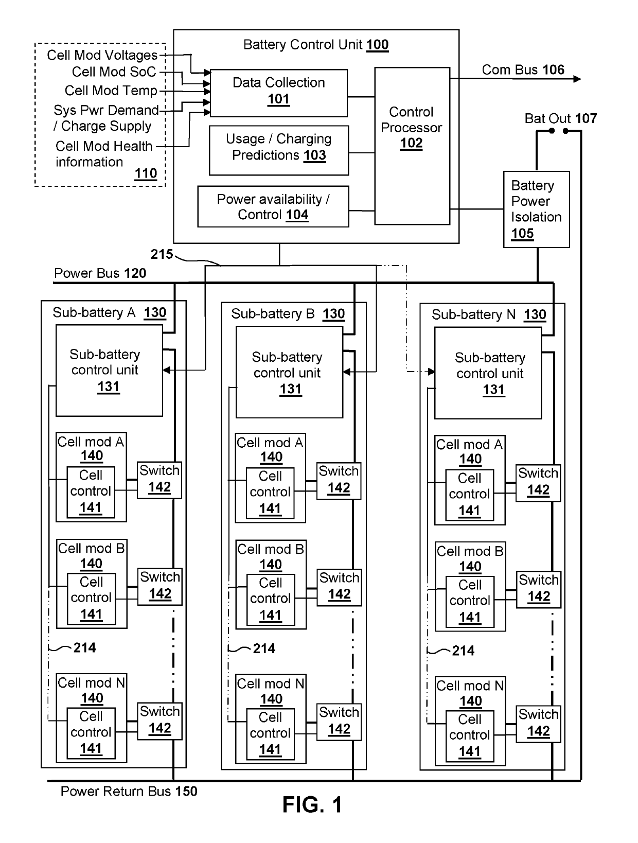
[0023]FIG. 1 shows a block diagram of a battery system according to an embodiment of the invention;

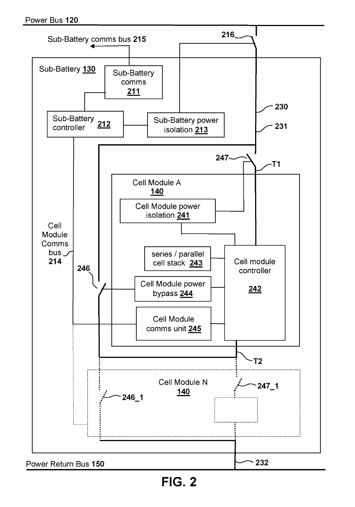
[0024]FIG. 2 shows a block diagram of a sub-battery forming part of the FIG. 1 embodiment;

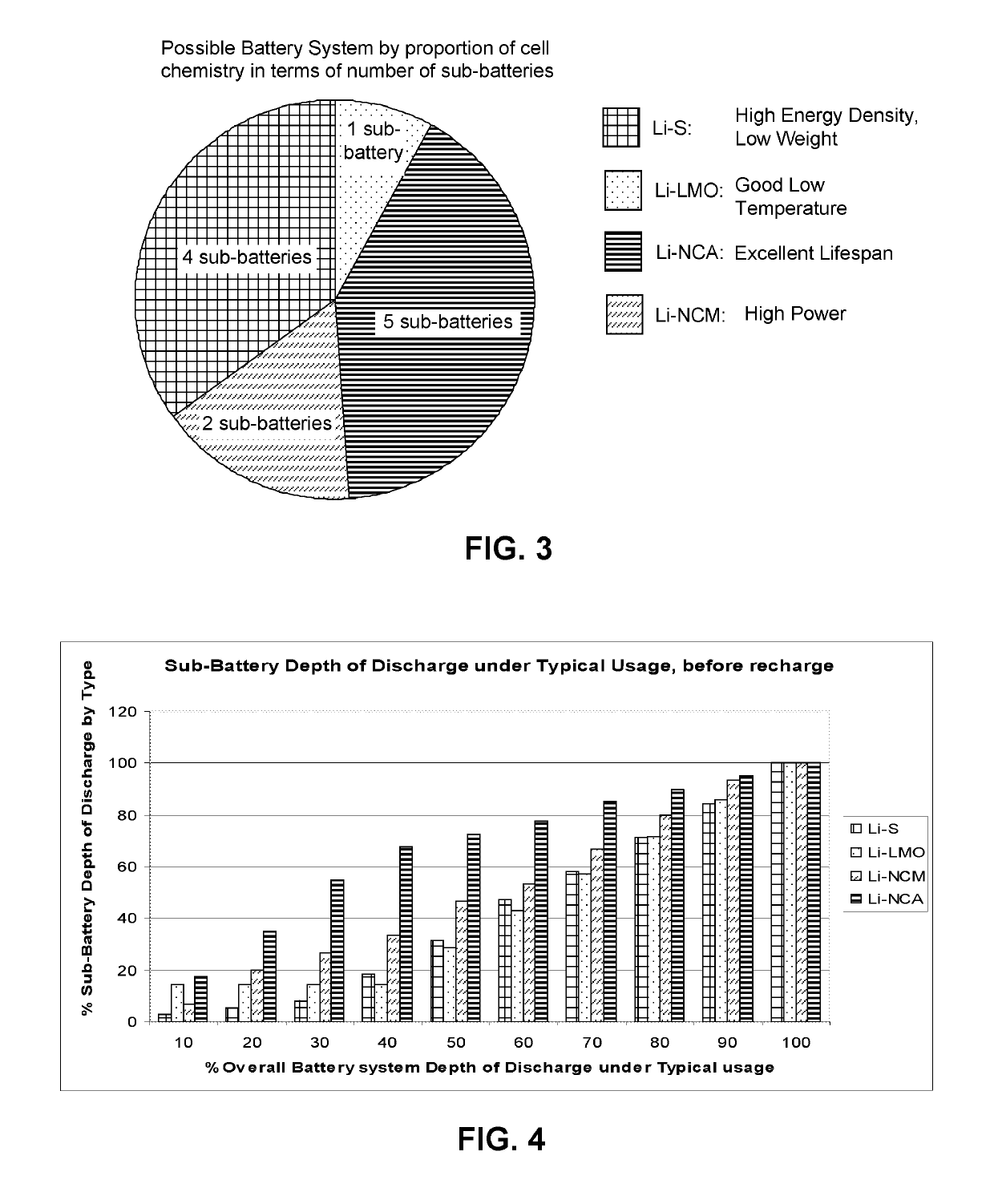
[0025]FIG. 3 shows a pie chart of the proportions of cell chemistries used in a battery system according to one implementation of the FIG. 1 embodiment; and

[0026]FIG. 4 shows a graph of sub-battery states of charge as the battery system of FIG. 3 is discharged.

[0027]The figures are not to scale, and same or similar reference signs denote same or similar features.

[0028]The block diagram of FIG. 1 shows a battery system with a battery control unit 100. The battery control unit 100 comprises a control processor 102 that is connected to a data collection unit 101, a usage / charging prediction unit 103, and a power availability / control unit 104. The contr...


PUM


Abstract

There is provided a battery system comprising a control system (102, 131, 41) and a plurality of sub-batteries (130) that have different battery chemistries to one another, resulting in different discharge characteristics to one another. The plurality of sub-batteries (130) are connected in parallel to one another for delivering power to an output (107), wherein each sub-battery comprises a plurality of cell modules (140) for connecting in series with one another to form a series circuit. The control system is configured to switch ones of the cell modules (140) in and out of the series circuits to control how many cell modules are connected in each series circuit, thereby controlling which ones of the sub batteries contribute most power to the output (107). A method for managing the battery system is also provided.

Description

[0001]The present invention relates to a battery system, for example for use in electric or hybrid electric vehicles (EV).BACKGROUND OF THE INVENTION[0002]A battery system for an EV for example has a requirement to provide high performance under acceleration, start under load in initially cold or hot conditions, provide a long endurance service life, provide a high energy density to minimise overall weight, and survive a suitable warranty period without defect, as well as being as affordably priced as possible. EV battery packs currently in the market consist of multiple cells of a chosen cell chemistry, with a performance tailored as the best compromise of all the above characteristics.[0003]Typically each type of cell chemistry has a particular internal impedance or electrical series resistance (ESR) that varies according to the rate of charge / discharge, and the temperature or age of the cells, and these generally differ from cell chemistry to cell chemistry.[0004]A single cell ch...

Claims


Application Information

Patent Timeline
Patent Type & Authority Patents(United States)
IPC IPC(8): B60L58/21H02J7/00G05F1/46
CPCG05F1/462H02J7/0024B60L58/21H02J2007/0067H02J7/0016Y02T10/7061H02J7/0063Y02T10/7055Y02T10/7005H02J2310/48H02J7/0025Y02T10/70B60L58/22B60L58/10
Inventor HALE, CHRISTOPHER J.
Owner UPGRADE TECH ENG
Why Eureka
Try Eureka