Optical sensor device, sensor apparatus, cable and method of manufacturing

a sensor and optical sensor technology, applied in the field of optical sensor devices, can solve the problems of manufacturing, performance and handling problems becoming prohibitive, and the minimum stiffness setting a limit to the obtainable sensitivity, and achieve the effect of stable deflection position

Active Publication Date: 2019-10-22
OPTICS11 BV +1
View PDF7 Cites 3 Cited by
  • Summary
  • Abstract
  • Description
  • Claims
  • Application Information

AI Technical Summary

Benefits of technology

[0010]This minimum diameter in combination with the material of choice determines the minimum achievable stiffness of the optical fiber including the intrinsic fiber optic sensor. Because of the interrelation with other characteristics of a sensor design, this minimum stiffness sets a limit to the obtainable sensitivity. This may be understood as follows. In a strain based system, the strain of the optical fiber including the intrinsic fiber optic sensor is used to obtain the required information for sensing. For example, in an accelerometer based on an FBG, the input action on the sensor will be a vibration which is converted into a periodic strain variation of the fiber. This causes the reflected wavelength of the FBG to vary correspondingly, as it is linearly dependent on the strain in the fiber, and the variation in reflected wavelength can be determined very accurately (e.g. with an interferometer or a spectral analyzer). However, it may be understood that the sensitivity of such a system increases in case the amount of stretching and shortening responsive to a given input action can be increased—the more the fiber is stretched in response to a given input action, the better input actions of smaller magnitude can be sensed.
[0020]In accordance with some further embodiments, the bi-stable spring comprises a deflection element and one or more leaf springs, the leaf springs connecting the deflection element with a fixed element, wherein the fixed element is fixed with respect to the reference body. The one or more leaf springs connect the deflection element to the fixed element in such a manner as to provide the deflection element with the first and a second stable deflection position. Such a bi-stable spring allows compact installation in an optical sensor device that may be made small in size. In some embodiments, the leaf springs of the bi-stable spring are buckled by pre-stressing these during manufacturing.

Problems solved by technology

For example, there is a limitation in minimum achievable diameter for glass fibers including an FBG.
Beyond the minimum diameter achievable (i.e. at even smaller diameters), manufacturing, performance and handling issues become prohibitive.
Because of the interrelation with other characteristics of a sensor design, this minimum stiffness sets a limit to the obtainable sensitivity.

Method used


Image

  • Optical sensor device, sensor apparatus, cable and method of manufacturing
  • Optical sensor device, sensor apparatus, cable and method of manufacturing
  • Optical sensor device, sensor apparatus, cable and method of manufacturing

Examples


Embodiment Construction

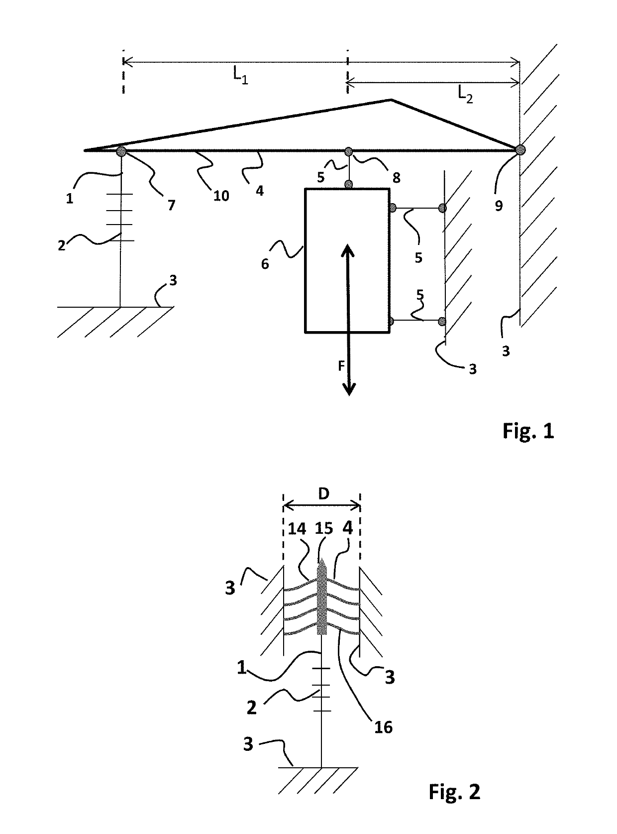
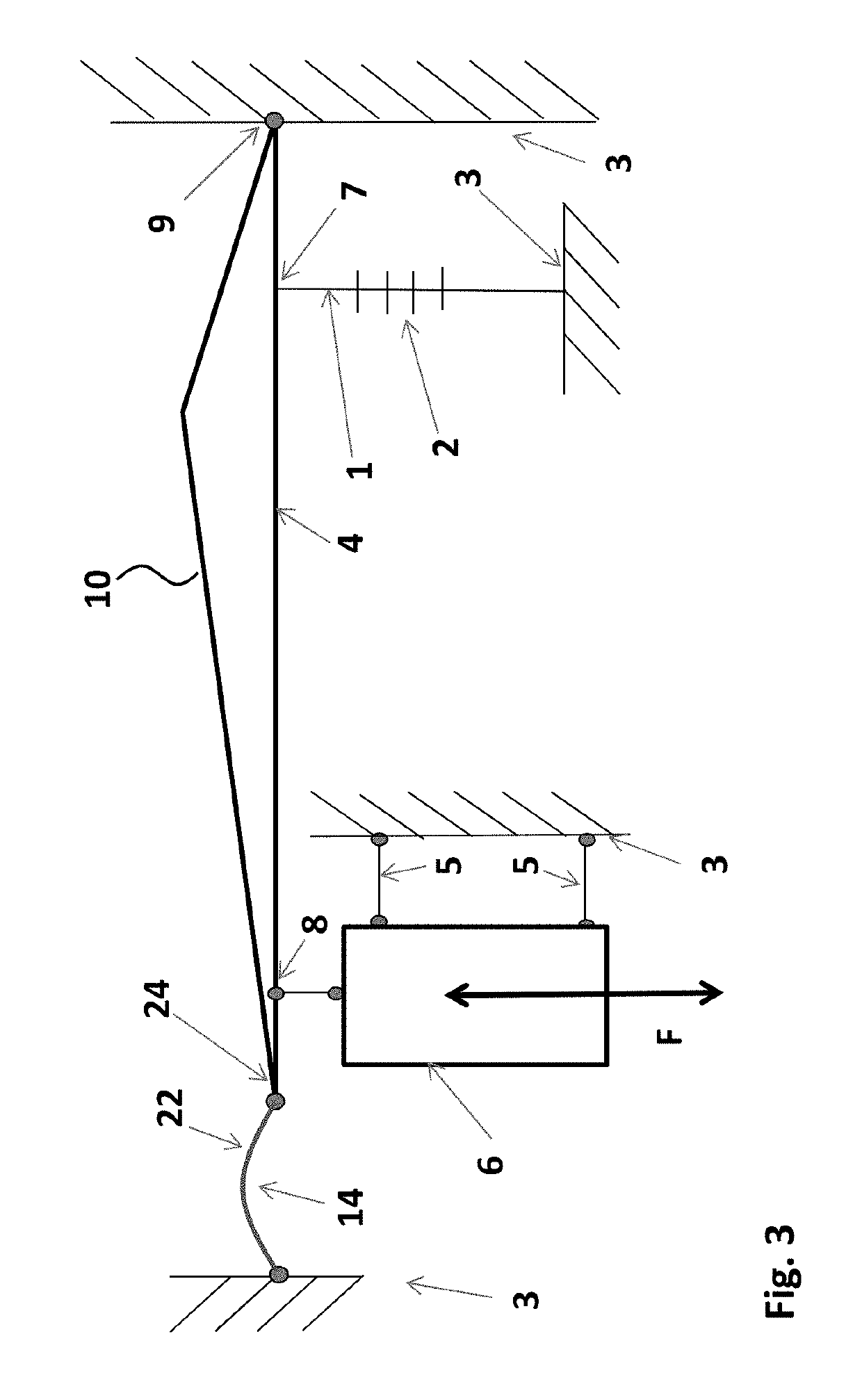
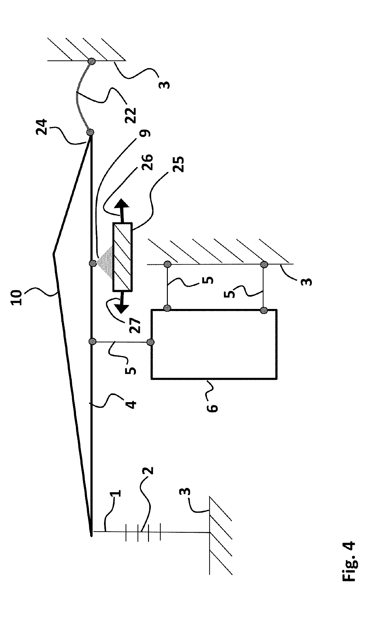
[0038]The advantages of the optical sensor device of present invention may become more clear by considering the sensitivity of an optical accelerometer. In the exemplary accelerometer of FIG. 1, a sensing element 6 is formed by an inertial mass. The sensing element 6 is arranged for receiving an input action F, e.g. a vibration as is schematically indicated by the double arrow. The sensing element 6 is connected to a fixed reference body 3 by means of hingeable connections 5, and further to a transmission arm 10 by a further hingeable connection 5 at location 8 along the arm 10. The transmission arm 10 is part of transmission structure 4, and is connected by a pivot 9 to the fixed reference body 3. Moreover, at location 7 along the transmission arm 10, an optical fiber 1 comprising a fiber bragg grating (FBG) 2 is connected thereto. The optical fiber 1 comprising the FBG 2 is further connected to the fixed reference body 3 on its other end with respect to the FBG 2. As may be apprec...


PUM

PropertyMeasurementUnit
diameteraaaaaaaaaa
stiffnessaaaaaaaaaa
transmission ratioaaaaaaaaaa

Abstract

The invention is directed at an optical sensor device, comprising a sensing element for receiving an input action, an optical fiber comprising an intrinsic fiber optic sensor, and a transmission structure arranged for exerting a sensing action on the optical fiber in response to the input action received by the sensing element, wherein the optical fiber in a first connecting part thereof is connected to a reference body and wherein the optical fiber in a second connecting part thereof is to the transmission structure for receiving the sensing action, the first connecting part and the second connecting part of the optical fiber being located on either side of the intrinsic fiber optic sensor, wherein the transmission structure comprises a bi-stable spring having a first and a second stable deflection position and a negative stiffness range around an unstable equilibrium position between the first and second stable deflection position, and wherein the optical fiber between the transmission structure and the reference body is pre-stressed such as to be tensed, said optical fiber thereby acting as a spring having a first spring constant of positive value, wherein the optical fiber thereby counteracts a spring action of the bi-stable spring such as to operate the bi-stable spring in a deflection position range within the negative stiffness range, the deflection position range not including the unstable equilibrium position of the bi-stable spring.

Description

CROSS-REFERENCE TO RELATED APPLICATIONS[0001]This application is a national stage application of International Application No. PCT / NL2015 / 050320, which was filed on May 8, 2015, of which is incorporated by reference in its entirety.FIELD OF THE INVENTION[0002]The present invention relates to an optical sensor device, in particular an optical sensor device applying an intrinsic fiber optic sensor. The invention further relates to a method of manufacturing.BACKGROUND[0003]A known class of optical sensors for various applications includes the use of intrinsic fiber optic sensors. An intrinsic fiber optic sensor is a sensor that uses an optical fiber as sensing element. In many applications the intrinsic fiber optic sensor is lit (e.g. by a laser), and a change in the fiber due to an external cause (dependent on the type of sensor) results in a measurable change in the optical signal transmitted by or received from the sensor. A typical example of an intrinsic fiber optic sensor is a Fi...

Claims


Application Information

Patent Timeline
Patent Type & Authority Patents(United States)
IPC IPC(8): G01D5/34G01D5/353G01H9/00G01L5/00G01P15/093G01L1/24G01P15/08
CPCG01H9/004G01D5/35316G01D5/35377G01P15/093G01L1/246G01L5/0057G01P2015/0857G01P2015/0837
Inventor KNOPPERS, GERMAN ENRIQUEWAGEMAKERS, THOMAS THEODORUS NICOLAAS JOHANNESKARABACAK, DEVREZ MEHMETVAN BEELEN, RUDOLF KLAASMEULBLOK, BASTIAAN
Owner OPTICS11 BV
Why Eureka
Try Eureka