
Turboshaft engine for an aircraft equipped with an automatically-activated centraliser

a technology of centraliser and turboshaft, which is applied in the direction of machines/engines, seaplanes, etc., can solve the problems of power shaft not being held by its power bearing, oscillation of shaft, and damage to sealing systems and rolling bearings of turboshaft engines

Inactive Publication Date: 2019-10-29
TURBOMECA SA
View PDF8 Cites 0 Cited by
  • Summary
  • Abstract
  • Description
  • Claims
  • Application Information

AI Technical Summary

Benefits of technology

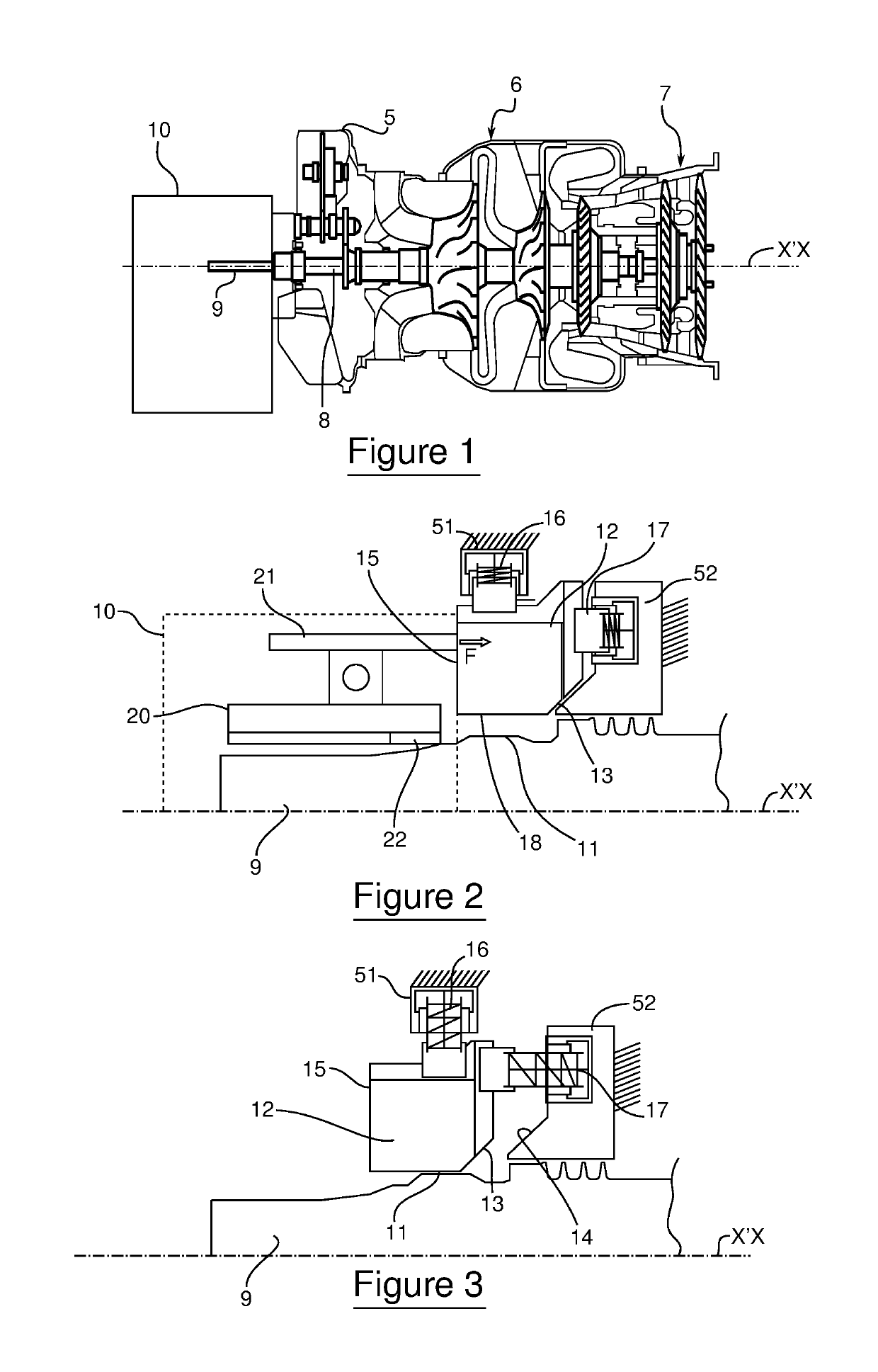
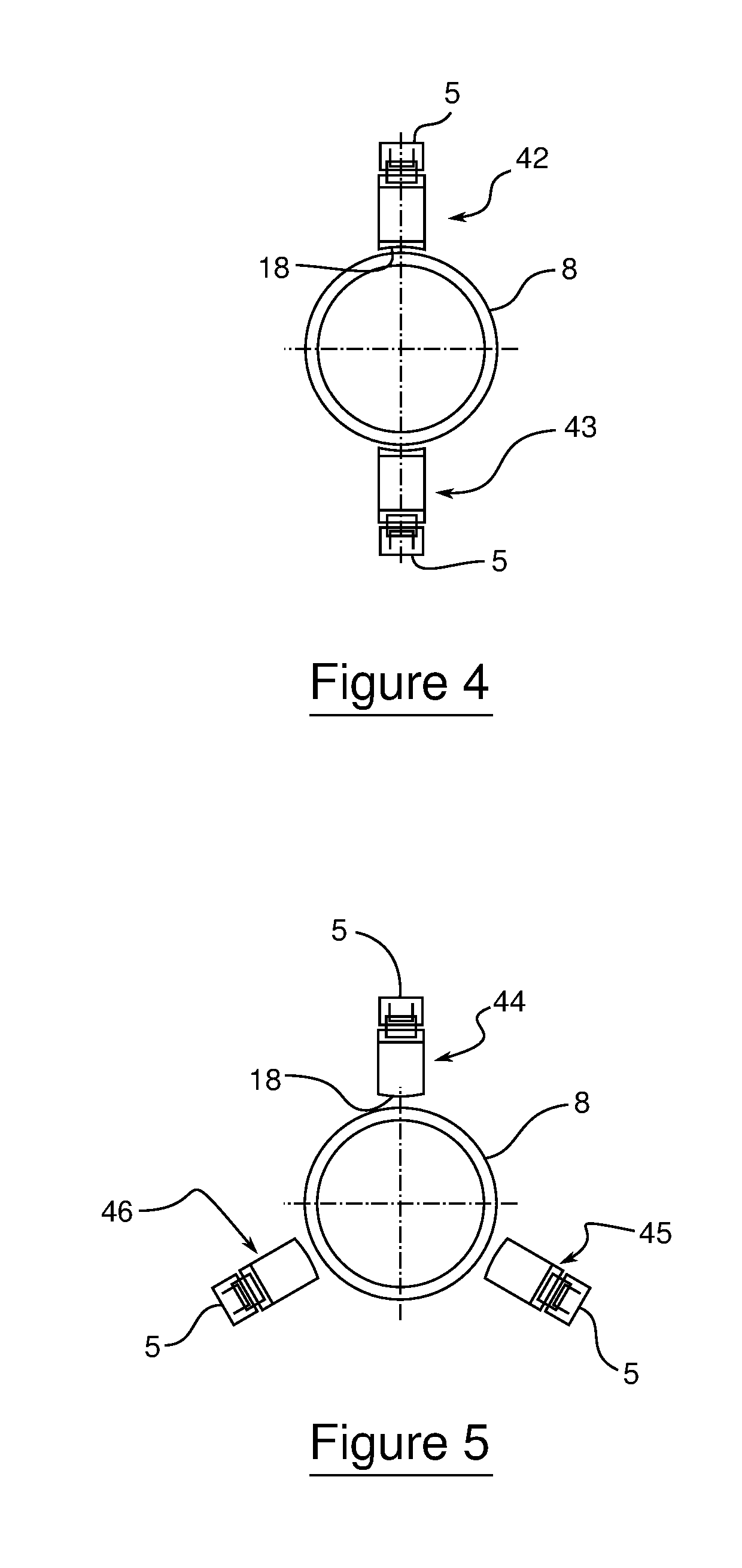
[0021]As this transition from the active position to the passive position and vice versa is automatic, the fitting of a turboshaft engine to, or its removal from, a reduction gearbox requires less vigilance in comparison with a turboshaft engine not fitted with the movable centraliser. This is because the movable centraliser forming a bearing for the power shaft positions itself automatically during removal of the turboshaft engine, and the centraliser releases the shaft automatically when the turboshaft engine is fitted to the reduction gearbox. The manipulation of a turboshaft engine according to this variant of the invention is therefore particularly easy for an operator during operations to fit / remove the turboshaft engine.

Problems solved by technology

One of the technical problems that results from this arrangement of the bearing for the power end of the power shaft in the reduction gearbox is that the power shaft is no longer held by its power bearing when it is not fitted into the reduction gearbox.
Consequently, in all situations where the turbine engine is not fitted into the reduction gearbox—for example, during transport of the turboshaft engine from a manufacturing or maintenance site to a site for fitting of the turboshaft engine to the aircraft, during storage of the turboshaft engine, etc.—there is a risk that the sealing systems and rolling bearings of the turboshaft engine will be impaired through radial oscillation of the shaft.
For example, a radial oscillation of the shaft may produce damage to a dynamic-seal type of sealing system that has a carbon ring or lip seal.

Method used


Image

  • Turboshaft engine for an aircraft equipped with an automatically-activated centraliser
  • Turboshaft engine for an aircraft equipped with an automatically-activated centraliser

Examples


Embodiment Construction

[0042]For the purposes of illustration and clarity, the figures are not drawn strictly to scale or in proportion. In the whole of the detailed description that follows with reference to the drawings, except where otherwise indicated, each element of the turboshaft engine is described as it is arranged when the turboshaft engine is in a position in which it is fitted horizontally to a reduction gearbox. This arrangement is shown, in particular, in FIG. 1. Furthermore, the word “axial” relates to locations along the central axis X′X of the turboshaft engine. The word “radial” relates to locations perpendicular to this central axis. Lastly, where elements in different drawings have the same reference signs, these elements are identical.

[0043]As shown in FIG. 1, a turboshaft engine according to the invention comprises a casing 5 in which are fitted a gas generator 6 and a free turbine 7. The free turbine 7 is integral with a power shaft 8. According to the embodiment in the drawings, th...


PUM


Abstract

A turboshaft engine includes a casing in which is arranged a gas generator and a free turbine fitted to a power shaft. The power shaft is configured to be mechanically connected to / disconnected from a reduction gearbox.The turboshaft engine includes at least one centralizer movable between an active position, in which the centralizer forms a bearing for the power shaft and which corresponds to a mechanical disconnection between the power shaft and the reduction gearbox, and a passive position, in which the centralizer is distanced from the power shaft and which corresponds to a mechanical connection between the power shaft the reduction gearbox.

Description

TECHNICAL FIELD OF THE INVENTION[0001]The invention relates to turboshaft engines for aircraft, in particular turboshaft engines comprising a free turbine of which one of the bearings is moved into a reduction gearbox.TECHNOLOGICAL BACKGROUND[0002]A turboshaft engine comprises, in a known manner, a gas generator and a free turbine fitted to a shaft, known as a power shaft. This power shaft is configured so that it can be connected mechanically to a reduction gearbox. This reduction gearbox is, for example, in the case of a helicopter, a power transmission gearbox connected to the rotor(s) of the helicopter. When the power shaft of the free turbine and the reduction gearbox are mechanically connected, the power of the power shaft is transmitted to the power transmission gearbox, which allows the rotor(s) of the helicopter to be driven in rotation.[0003]The power shaft of the free turbine is driven in rotation by the free turbine, which receives the gases produced by the gas generator...

Claims


Application Information

Patent Timeline
Patent Type & Authority Patents(United States)
IPC IPC(8): F02C7/36B64C27/12B64D35/02F16H57/02F01D15/12B64C35/02F02C3/10
CPCB64C27/12F02C7/36F01D15/12F02C3/10B64D35/02F16H2057/02043F05D2260/4031F05D2220/329Y02T50/671F05D2260/52F16H57/02F05D2230/68Y02T50/60B64D35/00
Inventor LAFARGUE, OLIVIERBROTIER, SÉBASTIEN
Owner TURBOMECA SA
Learn More