Optomechanical gyroscope utilizing the Sagnac effect

a gyroscope and sagnac technology, applied in measurement devices, instruments, surveying and navigation, etc., can solve problems such as the change of the position of interference fringes, and achieve the effect of improving the sensitivity to rotation and reducing the size of the fringes

Active Publication Date: 2019-10-29
NAT TECH & ENG SOLUTIONS OF SANDIA LLC
View PDF10 Cites 6 Cited by
  • Summary
  • Abstract
  • Description
  • Claims
  • Application Information

AI Technical Summary

Benefits of technology

[0007]Rotation is detected through its effect on the mechanical angular frequency of a circulating optical resonator. Optomechanical oscillation arises because of the radiation pressure exerted on the circulating optical resonator by circulating light. Through the optomechanical spring effect, the mechanical angular frequency is sensitive to the optical flux within the circulating optical resonator. In turn, the optical flux depends on the amount of detuning between the circulating optical resonator and the optical frequency of the laser that drives it. The Sagnac effect provides the link between the amount of detuning and the externally imposed angular rotation of the circulating optical resonator.
[0008]The Sagnac effect is an interference phenomenon caused by rotation. A beam of light is split and one of the two resultant beams is injected into a circulating optical resonator that may be subject to rotation. In other embodiments, the two beams are both injected into the same circulating optical resonator, but in opposite directions. In yet other embodiments, the two beams are injected into two separate, but identical, circulating optical resonators, again in opposite directions. In each case, upon exiting the circulating optical resonator(s), the light beams are combined and undergo interference. The relative phases of the two beams, and thus the position of the interference fringes, are shifted according to the angular velocity of the circulating optical resonator(s). In operation, when the Sagnac OM gyroscope is irrotational, i.e., when the circulating optical resonator(s) is not rotating, the two beams travel at a constant speed and the position of the interference fringes does not change. However, when the Sagnac OM gyroscope is rotated, one beam will slow with respect to the other beam causing the position of the interference fringes to change.
[0009]Analysis of the Sagnac OM gyroscope has shown that reducing its size improves its sensitivity to rotation as measured by a scale factor equal to the ratio of the change in the mechanical angular frequency to the externally imposed angular rotation frequency.

Problems solved by technology

However, when the Sagnac OM gyroscope is rotated, one beam will slow with respect to the other beam causing the position of the interference fringes to change.

Method used


Image

  • Optomechanical gyroscope utilizing the Sagnac effect
  • Optomechanical gyroscope utilizing the Sagnac effect
  • Optomechanical gyroscope utilizing the Sagnac effect

Examples


Embodiment Construction

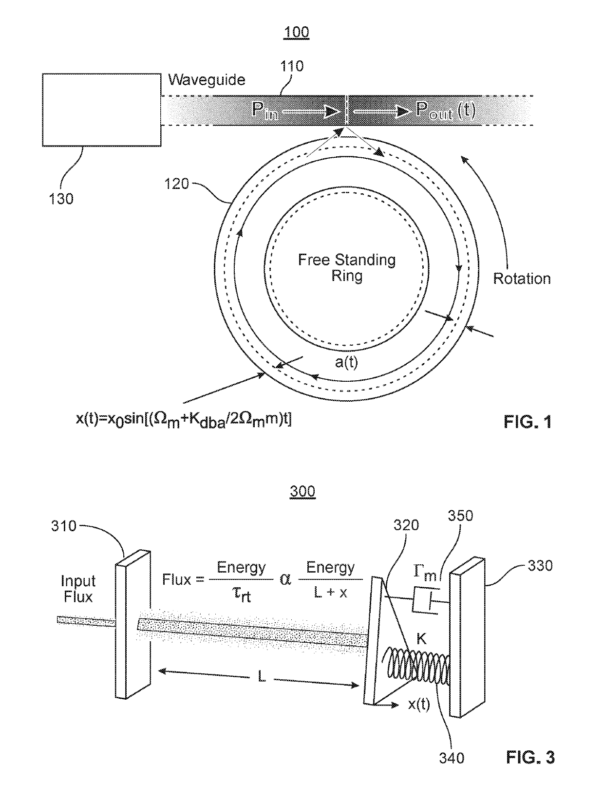
[0029]As illustrated in FIG. 1, a Sagnac OM gyroscope 100 in accordance with at least one embodiment includes a waveguide 110 evanescently coupled to an effectively free-standing circulating optical resonator 120 configured, e.g., as an optical micro-ring or micro-disk resonator. As is known in the art, the circulating optical resonator 120 can be made effectively free-standing by undercutting it with a suitable etchant in a process referred to as a release. In at least one embodiment of the invention, a released micro-ring circulating optical resonator is suspended over the substrate by laterally extending spokes or the like. In at least one other embodiment of the invention, a released micro-disk circulating optical resonator is supported from below by a pedestal.

[0030]For convenience, the geometrical configuration of the circulating optical resonator in the following discussion will be referred to as a “disk.” However, this terminology is to be understood as non-limiting, and as ...


PUM


Abstract

An apparatus and a method for detecting rotation based on the Sagnac effect is disclosed. Input light having sufficient power is injected into a circulating optical resonator to thereby excite an optomechanical oscillation of the resonator at an instantaneous mechanical angular frequency. Rotation of the circulating optical resonator causes a change in a frequency of the optomechanical oscillation of the resonator, which in turn causes the instantaneous mechanical angular frequency to change. The optomechanical oscillation produces modulation sidebands in the resonating optical field at the instantaneous mechanical angular frequency and harmonics thereof, which are demodulated from the optical frequency by detection in a photodetector. Differences in the instantaneous mechanical angular frequency induced by rotation are detected by processing the photodetector output signal.

Description

CROSS-REFERENCE TO RELATED APPLICATION[0001]This application claims the benefit of U.S. Provisional Application No. 62 / 545,172, filed Aug. 14, 2017, which is incorporated herein by reference.ACKNOWLEDGEMENT OF GOVERNMENT SUPPORT[0002]This invention was made with Government support under Contract No. DE-NA0003525 awarded by the United States Department of Energy / National Nuclear Security Administration. The Government has certain rights in the invention.FIELD OF THE INVENTION[0003]The invention relates to optically resonant sensing devices, and more particularly to devices for sensing rotation.ART BACKGROUND[0004]Gyroscopes are important for applications in navigation, guidance, and control. Many of these applications would benefit from miniaturization due to concerns with system cost, size, weight, and power. However, the possibilities for miniaturization are limited because the designs for conventional gyroscopes tend to exhibit better sensitivity and resolution at larger scales.[0...

Claims


Application Information

Patent Timeline
Patent Type & Authority Patents(United States)
IPC IPC(8): G01C19/72G01C19/66
CPCG01C19/721G01C19/662
Inventor GRINE, ALEJANDRO J.SERKLAND, DARWIN K.WOOD, MICHAEL
Owner NAT TECH & ENG SOLUTIONS OF SANDIA LLC
Why Eureka
Try Eureka